Arduino Due: Unleash 32-bit ARM Power for Advanced Projects
The Arduino Due is a powerful 32-bit ARM Cortex-M3 microcontroller board that offers significantly more processing power and memory than its 8-bit AVR-based predecessors.
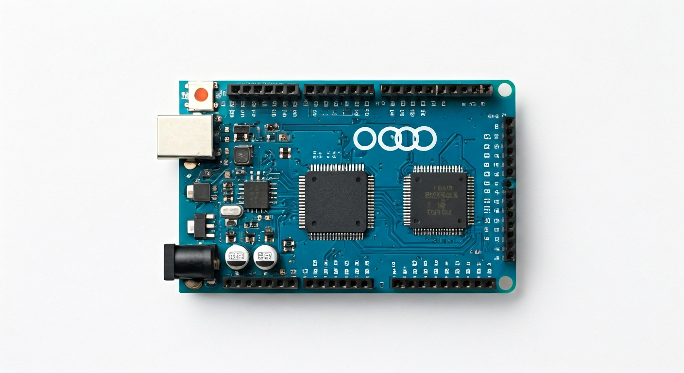
The Arduino Due represents a significant leap forward in the Arduino ecosystem, moving from the familiar 8-bit AVR microcontrollers to a much more powerful 32-bit ARM Cortex-M3 processor. Released in 2012, it was designed to meet the growing demand for higher performance in embedded projects, enabling more complex computations, faster data processing, and the handling of larger programs. This board is ideal for makers, students, and engineers who have outgrown the limitations of standard Arduinos and require more speed, memory, and advanced peripherals for their creations.
At the heart of the Arduino Due is the Atmel SAM3X8E microcontroller. This chip provides a substantial upgrade in terms of clock speed, memory, and peripheral capabilities. Unlike the ATmega series found on boards like the Uno or Mega, the SAM3X8E operates at a much higher frequency and features a 32-bit architecture, allowing it to handle data more efficiently and execute instructions faster. This makes it suitable for applications requiring real-time control, signal processing, or interfacing with high-speed sensors and communication modules.
The Arduino Due sits in the higher-performance segment of the Arduino family. It bridges the gap between hobbyist-level boards and more professional embedded development platforms. Its 3.3V logic level is a key differentiator from the 5V logic of many other Arduinos, requiring careful consideration when interfacing with older or 5V-tolerant components. This board is particularly well-suited for projects involving motor control, advanced sensor networks, audio processing, or any application where the computational demands exceed the capabilities of typical 8-bit microcontrollers.
Watch
Related video, embedded from YouTube.
Specifications
| Microcontroller / SoC | Atmel SAM3X8E (ARM Cortex-M3) |
| Architecture | 32-bit ARMv7-M |
| Clock speed | 84 MHz |
| Flash / Storage | 512 KB (AT45DB321D flash memory, accessible via SPI) |
| RAM / SRAM | 96 KB (64 KB + 32 KB) |
| Operating voltage | 3.3V |
| Digital I/O pins | 54 (of which 12 can be used as PWM outputs) |
| Analog / ADC | 12-bit Analog-to-Digital Converters (12 channels) |
| DAC | 2 x 12-bit Digital-to-Analog Converters |
| PWM | 12 channels |
| Connectivity | I2C, SPI, UART |
| USB | 1 x Micro-USB (programming and native USB), 1 x USB Host (Type A) |
| Power input | 7-12V recommended (via DC barrel jack or USB) |
| Dimensions | 101.6 mm x 53.3 mm (4.0 in x 2.1 in) |
Pinout & pin functions
| Pin | Function |
|---|---|
| 3.3V | Power output (regulated 3.3V) |
| GND | Ground |
| IOREF | Voltage reference for the I/O pins (typically 3.3V) |
| Reset | System reset pin |
| D0 (RX0) | Digital I/O, UART RX |
| D1 (TX0) | Digital I/O, UART TX |
| D2 | Digital I/O |
| D3 | Digital I/O |
| D4 | Digital I/O |
| D5 | Digital I/O |
| D6 | Digital I/O |
| D7 | Digital I/O |
| D8 | Digital I/O |
| D9 | Digital I/O, PWM |
| D10 (SS) | Digital I/O, SPI SS |
| D11 (MOSI) | Digital I/O, SPI MOSI |
| D12 (MISO) | Digital I/O, SPI MISO |
| D13 (SCK) | Digital I/O, SPI SCK |
| D14 (SCL) | Digital I/O, I2C SCL |
| D15 (SDA) | Digital I/O, I2C SDA |
| D16 | Digital I/O |
| D17 | Digital I/O |
| D18 | Digital I/O |
| D19 | Digital I/O |
| D20 | Digital I/O |
| D21 | Digital I/O |
| D22 | Digital I/O |
| D23 | Digital I/O |
| D24 | Digital I/O |
| D25 | Digital I/O |
| D26 | Digital I/O |
| D27 | Digital I/O |
| D28 | Digital I/O |
| D29 | Digital I/O |
| D30 | Digital I/O |
| D31 | Digital I/O |
| D32 | Digital I/O, PWM |
| D33 | Digital I/O, PWM |
| D34 | Digital I/O |
| D35 | Digital I/O |
| D36 | Digital I/O |
| D37 | Digital I/O |
| D38 | Digital I/O |
| D39 | Digital I/O |
| D40 | Digital I/O |
| D41 | Digital I/O |
| A0 | Analog Input, Digital I/O |
| A1 | Analog Input, Digital I/O |
| A2 | Analog Input, Digital I/O |
| A3 | Analog Input, Digital I/O |
| A4 | Analog Input, Digital I/O |
| A5 | Analog Input, Digital I/O |
| A6 | Analog Input, Digital I/O |
| A7 | Analog Input, Digital I/O |
| A8 | Analog Input, Digital I/O |
| A9 | Analog Input, Digital I/O |
| A10 | Analog Input, Digital I/O |
| A11 | Analog Input, Digital I/O |
| A12 | Analog Input, Digital I/O |
| A13 | Analog Input, Digital I/O |
| A14 | Analog Input, Digital I/O |
| A15 | Analog Input, Digital I/O |
| AREF | Analog Reference voltage |
| DAC0 | Analog Output (12-bit DAC) |
| DAC1 | Analog Output (12-bit DAC) |
| USB_DM | USB Data - |
| USB_DP | USB Data + |
| USB_HOST_DM | USB Host Data - |
| USB_HOST_DP | USB Host Data + |
| VBAT | Battery voltage input (for power management) |
| 3.3V | Power output (regulated 3.3V) |
| 5V | Power output (regulated 5V, from USB or VIN) |
| GND | Ground |
Wiring & circuit basics
The Arduino Due operates at a 3.3V logic level. This is a crucial difference from 5V boards like the Arduino Uno. Connecting 5V signals directly to the Due's I/O pins can damage the microcontroller. When interfacing with 5V sensors or modules, a logic level shifter is necessary. Conversely, if you are using 3.3V sensors with a 5V Arduino, you might need to boost the signal. Always ensure your power supply is adequate; the DC barrel jack can accept 7-12V, which is regulated down to 3.3V and 5V on the board. The USB ports also provide 5V power.
Powering the Due safely involves using the USB port for low-power applications or the DC barrel jack for higher current needs. The board has onboard regulators to supply 3.3V and 5V. For example, to power an LED, connect its anode to a digital pin (e.g., D13) and its cathode through a current-limiting resistor (typically 220-330 ohms for a standard LED) to a GND pin. This resistor protects both the LED and the Arduino's output pin from excessive current.
When connecting I2C devices, use pins D14 (SCL) and D15 (SDA). These pins are multiplexed with standard digital I/O but are specifically designated for I2C communication. Remember that I2C devices often require pull-up resistors on both the SCL and SDA lines; the Arduino Due does not have onboard pull-up resistors for these pins, so you will need to add them externally (typically 4.7k ohm to 3.3V).
Programming & getting started
The primary toolchain for the Arduino Due is the Arduino IDE, which supports the SAM architecture. After installing the IDE, you'll need to add the Arduino SAMD Boards package via the Boards Manager (Tools > Board > Boards Manager). Once installed, select the 'Arduino Due (Programming Port)' or 'Arduino Due (Native USB)' from the Tools > Board menu. The Due has two USB ports: the 'Programming Port' (Micro-USB) is typically used for uploading sketches via a standard UART bridge, while the 'Native USB' port (USB-A) can be used for more advanced USB functions like implementing HID or CDC devices directly from the microcontroller.
To upload your first program, connect the Due to your computer using the Micro-USB cable to the 'Programming Port'. Open a simple sketch, like the 'Blink' example (File > Examples > 01.Basics > Blink), verify it (Sketch > Verify/Compile), and then upload it (Sketch > Upload). The onboard LED (often labeled 'L') should start blinking. For more advanced development, PlatformIO integrated into VS Code offers excellent support for the Arduino Due, providing features like code completion, debugging, and easier library management.