Arduino Mega 2560: The Ultimate Board for Ambitious Projects
The Arduino Mega 2560 is a powerful microcontroller board with extensive I/O, making it ideal for complex projects requiring many sensors, actuators, or communication interfaces.
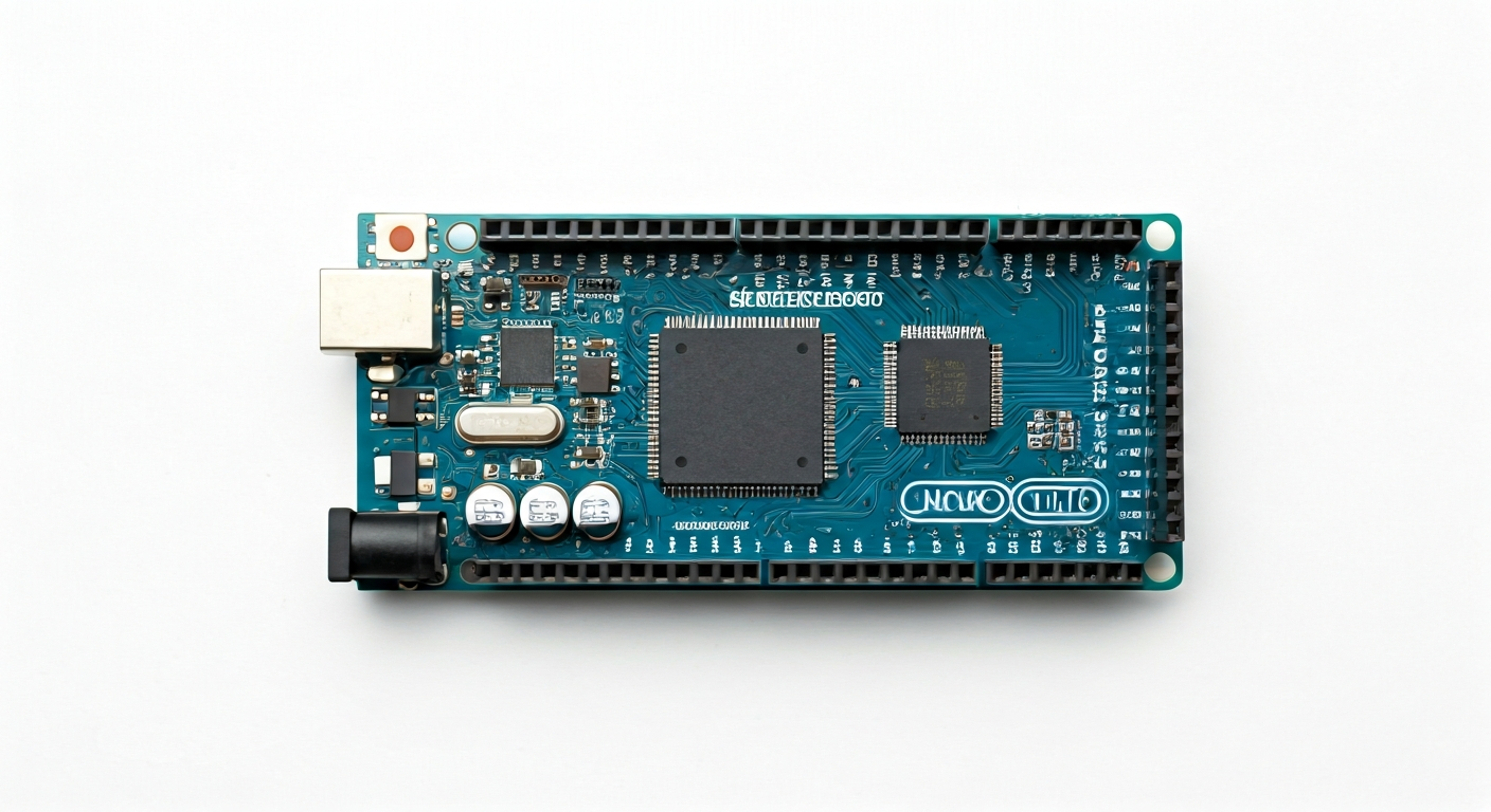
The Arduino Mega 2560 is a flagship board in the Arduino family, designed for users who need more processing power, memory, and input/output (I/O) pins than typically found on the Arduino Uno. Released around 2010, it quickly became a favorite for hobbyists, students, and engineers tackling larger, more demanding projects.
At its heart lies the Atmel ATmega2560 microcontroller, a 16-bit AVR-based chip. This powerful processor, running at 16 MHz, provides a significant step up from the ATmega328P found on the Uno, offering more program storage, RAM, and a vastly expanded set of peripherals. The Mega 2560 is particularly well-suited for applications that involve extensive data logging, complex control systems, or interfacing with multiple communication protocols simultaneously.
Compared to its smaller siblings, the Mega 2560 boasts 54 digital I/O pins (15 of which can be used for PWM output), 16 analog inputs, and 4 UARTs (hardware serial ports). This abundance of I/O makes it an excellent choice for robotics, 3D printers, home automation systems, and multi-axis CNC machines where numerous sensors and actuators need to be managed. Its robust feature set and widespread community support solidify its position as a go-to board for ambitious Arduino projects.
The Arduino Mega 2560 is designed for makers who have outgrown the pin count or memory limitations of smaller boards like the Arduino Uno. If your project involves connecting many sensors, driving multiple motors, displaying information on large screens, or communicating over several serial interfaces, the Mega 2560 provides the necessary resources without compromise. Its ease of use, combined with its extensive capabilities, makes it a versatile platform for both learning and professional development.
Watch
Related video, embedded from YouTube.
Specifications
| Microcontroller / SoC | Atmel ATmega2560 |
| Architecture | AVR (8-bit) |
| Clock speed | 16 MHz |
| Flash / Storage | 256 KB (of which 8 KB used by bootloader) |
| RAM / SRAM | 8 KB |
| Operating voltage | 5V |
| Digital I/O pins | 54 (15 support PWM) |
| Analog / ADC | 16 analog inputs (10-bit resolution) |
| PWM | 15 pins (marked with '~') |
| Connectivity | 4 UARTs (Serial), SPI, I2C |
| USB | ATmega16U2 (for USB-to-serial communication) |
| Power input | 7-12V recommended (via DC barrel jack or USB) |
| Dimensions | 101.6 mm x 53.3 mm |
Pinout & pin functions
| Pin | Function |
|---|---|
| 5V | Power output (regulated 5V) |
| 3.3V | Power output (regulated 3.3V) |
| GND | Ground |
| GND | Ground |
| IOREF | Voltage reference for I/O pins |
| RESET | Resets the microcontroller |
| 0 (RXD) | Hardware Serial 0 RX pin |
| 1 (TXD) | Hardware Serial 0 TX pin |
| 2 | Digital I/O |
| 3 | Digital I/O, PWM |
| 4 | Digital I/O |
| 5 | Digital I/O, PWM |
| 6 | Digital I/O, PWM |
| 7 | Digital I/O |
| 8 | Digital I/O |
| 9 | Digital I/O, PWM |
| 10 | Digital I/O, PWM, SPI MOSI |
| 11 | Digital I/O, PWM, SPI SCK |
| 12 | Digital I/O, SPI MISO |
| 13 | Digital I/O, SPI SS |
| 14 (SCL) | I2C Clock |
| 15 (SDA) | I2C Data |
| 16 | Digital I/O |
| 17 | Digital I/O |
| 18 | Digital I/O |
| 19 | Digital I/O |
| 20 | Digital I/O |
| 21 | Digital I/O |
| 22 | Digital I/O |
| 23 | Digital I/O |
| 24 | Digital I/O |
| 25 | Digital I/O |
| 26 | Digital I/O |
| 27 | Digital I/O |
| 28 | Digital I/O |
| 29 | Digital I/O |
| 30 | Digital I/O |
| 31 | Digital I/O |
| 32 | Digital I/O, UART 1 TX |
| 33 | Digital I/O, UART 1 RX |
| 34 | Digital I/O, UART 2 TX |
| 35 | Digital I/O, UART 2 RX |
| 36 | Digital I/O, UART 3 TX |
| 37 | Digital I/O, UART 3 RX |
| 38 | Digital I/O, UART 4 TX |
| 39 | Digital I/O, UART 4 RX |
| 40 | Digital I/O |
| 41 | Digital I/O |
| 42 | Digital I/O |
| 43 | Digital I/O |
| 44 | Digital I/O |
| 45 | Digital I/O |
| 46 | Digital I/O |
| 47 | Digital I/O |
| 48 | Digital I/O |
| 49 | Digital I/O |
| 50 | Digital I/O, I2C SDA |
| 51 | Digital I/O, I2C SCL |
| 52 | Digital I/O |
| 53 | Digital I/O |
| A0 | Analog Input 0 |
| A1 | Analog Input 1 |
| A2 | Analog Input 2 |
| A3 | Analog Input 3 |
| A4 | Analog Input 4 |
| A5 | Analog Input 5 |
| A6 | Analog Input 6 |
| A7 | Analog Input 7 |
| A8 | Analog Input 8 |
| A9 | Analog Input 9 |
| A10 | Analog Input 10 |
| A11 | Analog Input 11 |
| A12 | Analog Input 12 |
| A13 | Analog Input 13 |
| A14 | Analog Input 14 |
| A15 | Analog Input 15 |
| AREF | Analog Reference voltage |
| GND | Ground |
| VIN | Power input (7-12V recommended) |
Wiring & circuit basics
The Arduino Mega 2560 operates at a logic level of 5V, meaning its digital pins HIGH state is 5V and LOW is 0V. When connecting external components, especially those designed for 3.3V logic, use a level shifter to prevent damage. Powering the board can be done via the USB port (typically 5V, limited current) or the DC barrel jack. The barrel jack accepts a voltage range of 7-12V, with an onboard voltage regulator stepping it down to 5V for the board's operation. It's crucial to use a power supply within this range; exceeding 12V can overheat the regulator, and using less than 7V might not provide sufficient power.
For a simple LED circuit, connect the longer leg (anode) of an LED to a digital pin (e.g., Pin 13) and the shorter leg (cathode) to one end of a current-limiting resistor (typically 220-330 ohms). Connect the other end of the resistor to a GND pin. This setup ensures that the current flowing through the LED is controlled, preventing it from burning out. The Arduino IDE's 'Blink' example is a great starting point for testing digital output.
Connecting an I2C device, such as a common LCD display or a sensor module, is straightforward. The Mega 2560 has dedicated pins for I2C: SDA (Serial Data) on Pin 20 (and also A4) and SCL (Serial Clock) on Pin 21 (and also A5). Connect the SDA pin of your device to the Mega's SDA pin, and the SCL pin of your device to the Mega's SCL pin. Ensure both the device and the Mega are powered and grounded correctly. Remember that I2C devices also require pull-up resistors on the SDA and SCL lines, which are often built into breakout boards or can be added externally.
Programming & getting started
The primary toolchain for the Arduino Mega 2560 is the Arduino IDE, available for Windows, macOS, and Linux. Download and install the latest version from the official Arduino website. Once installed, connect your Mega 2560 to your computer via USB. In the IDE, select 'Arduino Mega or Mega 2560' from the Tools > Board menu and choose the correct COM port under Tools > Port. To upload your first program, select the 'Blink' example from File > Examples > 01.Basics, then click the Upload button. The IDE will compile the code and flash it to the microcontroller.
For more advanced development, PlatformIO with Visual Studio Code offers a more robust environment with features like code completion, debugging, and library management. Alternatively, MicroPython and CircuitPython can be used, though support for the ATmega2560 on the Mega 2560 might be less mature compared to boards with ARM Cortex-M processors. For very low-level control or integration into larger systems, C/C++ with AVR-GCC toolchains can be employed.