Arduino Nano: The Compact Powerhouse for Your Projects
A small, breadboard-friendly microcontroller board offering the core Arduino experience in a tiny form factor.
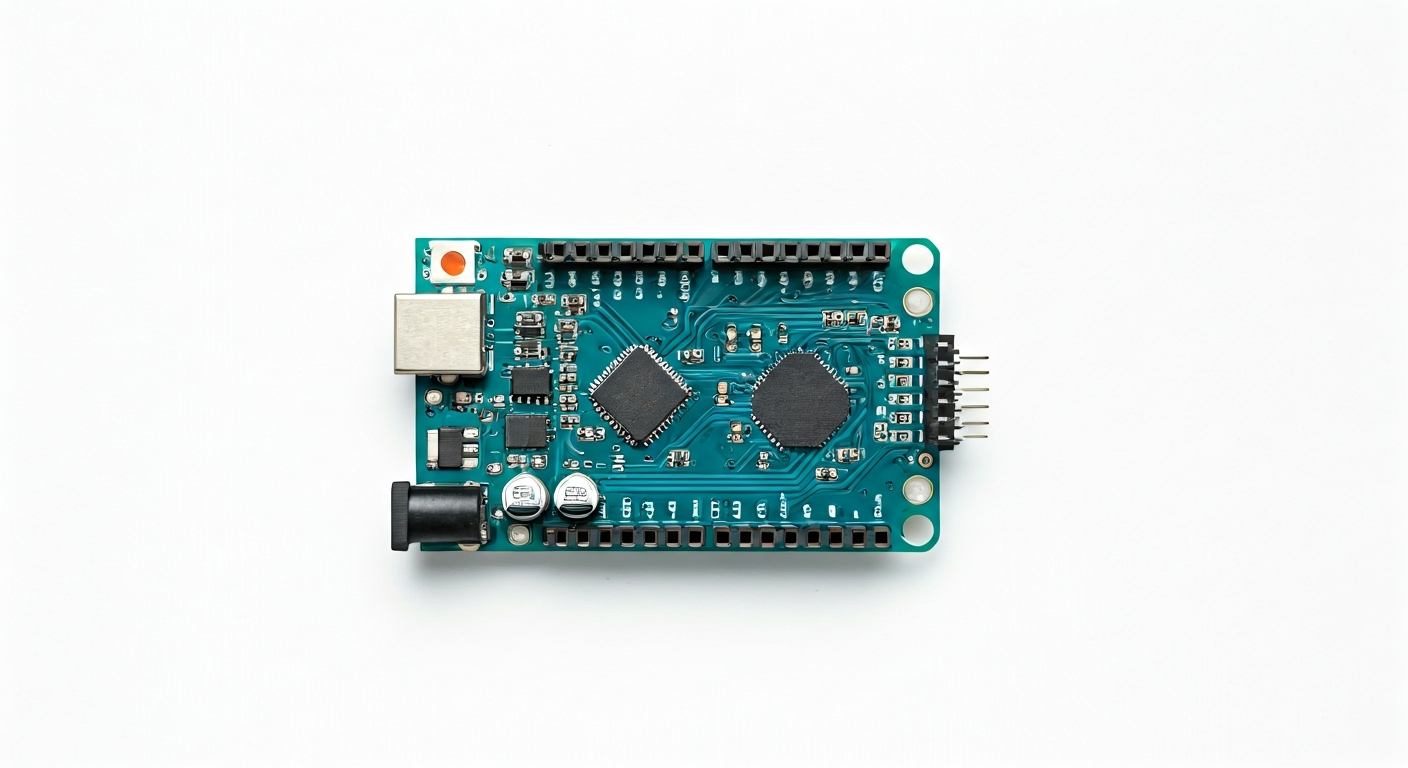
The Arduino Nano is a compact and versatile microcontroller board based on the ATmega328P microcontroller. Released in 2008, it was designed to offer the full functionality of the larger Arduino Uno but in a much smaller, breadboard-compatible package. This makes it ideal for projects where space is a constraint, such as wearables, compact robots, or embedded sensor nodes.
At its heart, the Arduino Nano features the ATmega328P, an 8-bit AVR RISC microcontroller. This chip provides a robust set of features including 32KB of Flash memory for program storage, 2KB of SRAM for variables, and 1KB of EEPROM for non-volatile data. It operates at a clock speed of 16MHz and uses a 5V logic level, which is common for many Arduino projects and shields, making it easy to interface with a wide range of sensors and modules.
Compared to other Arduino boards, the Nano strikes a balance between size and capability. It offers nearly the same I/O capabilities as the Arduino Uno but in a significantly smaller footprint. Its pin headers are designed to be directly plugged into breadboards without requiring any additional adapters, simplifying prototyping. This board is a favorite among hobbyists, students, and even professional engineers looking for a reliable and cost-effective solution for embedded applications that don't demand the high processing power or extensive connectivity of more advanced boards like the ESP32 or Raspberry Pi Pico.
The history of the Arduino Nano is tied to the growing need for smaller, more integrated development platforms. While initially a less common option, its breadboard-friendliness and robust ATmega328P core have cemented its place as a go-to board for countless projects. It’s particularly well-suited for beginners taking their first steps into physical computing, as well as experienced makers who need a dependable workhorse for iterative prototyping and final product integration where minimal size is key.
Watch
Related video, embedded from YouTube.
Specifications
| Microcontroller / SoC | ATmega328P |
| Architecture | 8-bit AVR RISC |
| Clock speed | 16 MHz |
| Flash / Storage | 32 KB (of which 0.5 KB used by bootloader) |
| RAM / SRAM | 2 KB |
| EEPROM | 1 KB |
| Operating voltage | 5V |
| Digital I/O pins | 22 (6 of which can be used as PWM outputs) |
| Analog / ADC | 8 (10-bit resolution) |
| PWM | 6 pins (3, 5, 6, 9, 10, 11) |
| Connectivity | — |
| USB | Mini-USB connector (for programming and power) |
| Power input | 7-12V recommended (via VIN pin or barrel jack if present on clone), 5V via USB or 5V pin |
| Dimensions | 18 mm x 48 mm |
Pinout & pin functions
| Pin | Function |
|---|---|
| GND | Ground |
| GND | Ground |
| 3.3V | 3.3V output (internal regulator) |
| RESET | Reset button (external) |
| A0 | Analog Input / Digital I/O |
| A1 | Analog Input / Digital I/O |
| A2 | Analog Input / Digital I/O |
| A3 | Analog Input / Digital I/O |
| A4 | Analog Input / Digital I/O, I2C SDA |
| A5 | Analog Input / Digital I/O, I2C SCL |
| A6 | Analog Input / Digital I/O |
| A7 | Analog Input / Digital I/O |
| D0 (RX) | Digital I/O, UART Receive |
| D1 (TX) | Digital I/O, UART Transmit |
| D2 | Digital I/O |
| D3 | Digital I/O, PWM |
| D4 | Digital I/O |
| D5 | Digital I/O, PWM |
| D6 | Digital I/O, PWM |
| D7 | Digital I/O |
| D8 | Digital I/O |
| D9 | Digital I/O, PWM |
| D10 (SS) | Digital I/O, SPI Slave Select |
| D11 (MOSI) | Digital I/O, SPI Master Out Slave In |
| D12 (MISO) | Digital I/O, SPI Master In Slave Out |
| D13 (SCK) | Digital I/O, SPI Serial Clock |
| 5V | 5V output (regulated) |
| VIN | Power input (7-12V recommended) |
Wiring & circuit basics
Powering the Arduino Nano is straightforward. You can supply power via the Mini-USB port, which is convenient for programming and testing. Alternatively, you can use the VIN pin, which accepts a voltage range of 7-12V and is regulated down to 5V by an onboard regulator. Be mindful of the current requirements of your project; the Nano's onboard regulator can typically handle up to 500mA, but it's good practice to stay within reasonable limits to avoid overheating. Always ensure your power supply is stable and within the specified voltage range to prevent damage to the board.
The Arduino Nano operates at a 5V logic level. This means that digital HIGH signals are typically 5V, and digital LOW signals are 0V. When interfacing with components that operate at a different logic level, such as 3.3V sensors, you will need a logic level shifter to prevent damage. For example, connecting a 3.3V sensor's output directly to a Nano's input pin might not be reliably read as HIGH, and connecting a 5V output from the Nano to a 3.3V input could damage the sensor.
A common beginner circuit is lighting an LED. Connect the anode (longer leg) of an LED to a digital pin, such as D9. Connect the cathode (shorter leg) of the LED to one end of a current-limiting resistor (e.g., 220-330 ohms). Connect the other end of the resistor to a GND pin on the Nano. When you set D9 to HIGH in your code, current will flow through the resistor and LED, illuminating it. The resistor protects the LED and the Arduino pin from excessive current. For an I2C sensor like a BME280, you would connect its VCC to the Nano's 5V pin, GND to a GND pin, SDA to A4, and SCL to A5.
Programming & getting started
The primary toolchain for the Arduino Nano is the Arduino IDE. Download and install the latest version from the official Arduino website. Once installed, select 'Arduino Nano' from the Tools > Board menu and choose the correct COM port associated with your Nano (after connecting it via USB). To upload your first program, the 'Blink' example sketch is a great starting point. Open it via File > Examples > 01.Basics > Blink, then click the Upload button. This will compile the code and flash it to the ATmega328P, causing the onboard LED (usually connected to D13) to blink.
For more advanced users, PlatformIO, integrated into VS Code, offers a more powerful development environment with features like advanced code completion, debugging, and library management. MicroPython and CircuitPython are also options for the ATmega328P, though they might require specific firmware flashing and may not offer the same performance as C/C++ sketches. The ATmega328P's bootloader allows for easy reprogramming over the serial connection provided by the USB-to-serial chip on the Nano.