Arduino Nano RP2040 Connect: Powering Your Projects with RP2040 and Wi-Fi
The Arduino Nano RP2040 Connect combines the versatile RP2040 microcontroller with built-in Wi-Fi and Bluetooth for connected embedded projects.
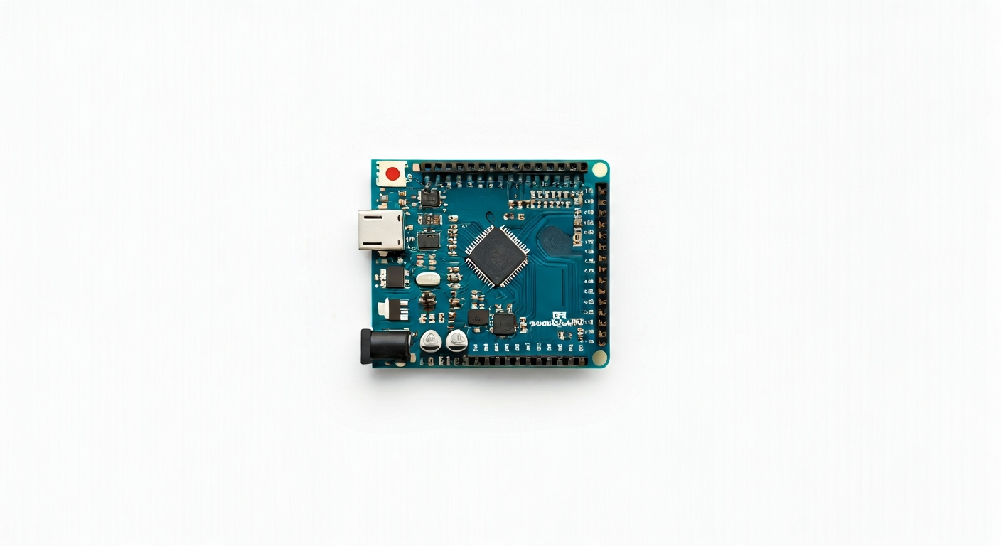
The Arduino Nano RP2040 Connect is a compact microcontroller board that bridges the gap between the popular Arduino Nano form factor and the powerful Raspberry Pi RP2040 chip. It's designed for makers, students, and engineers looking to create sophisticated, connected projects without the complexity of larger development boards. This board integrates a wealth of features, including wireless connectivity, making it ideal for IoT applications, robotics, and interactive installations.
At its heart is the Raspberry Pi RP2040, a dual-core ARM Cortex-M0+ processor clocked at up to 133 MHz. This chip is known for its flexibility, generous RAM, and unique Programmable I/O (PIO) peripherals, which allow for custom hardware interfaces. The RP2040 is manufactured by Raspberry Pi and was first introduced in the Raspberry Pi Pico, quickly gaining popularity for its performance and affordability. The Arduino Nano RP2040 Connect leverages this capable silicon and adds essential components for modern development.
This board sits within the Arduino family as a high-performance, connected option, building upon the familiar Nano footprint. It's a step up from basic Arduino boards like the Uno or the original Nano, offering significantly more processing power, more memory, and integrated wireless. Its target audience includes those who have outgrown simpler microcontrollers or require the connectivity and performance for more demanding applications. The inclusion of an onboard IMU (Inertial Measurement Unit) further expands its capabilities for motion-sensing projects.
Released around 2021, the Arduino Nano RP2040 Connect was a strategic move by Arduino to embrace the RP2040 ecosystem while providing their signature ease of use and extensive community support. It's particularly well-suited for projects that require real-time processing, complex sensor data handling, and seamless integration with the internet or local networks. The onboard Wi-Fi and Bluetooth, managed by a u-blox NINA-W102 module, make it a compelling choice for smart home devices, remote monitoring systems, and interactive art installations.
Watch
Related video, embedded from YouTube.
Specifications
| Microcontroller / SoC | Raspberry Pi RP2040 |
| Architecture | Dual-core ARM Cortex-M0+ |
| Clock speed | 133 MHz (default, can be overclocked) |
| Flash / Storage | 16 MB (external QSPI Flash) |
| RAM / SRAM | 264 KB (on-chip SRAM) |
| Operating voltage | 3.3V |
| Digital I/O pins | 20 (shared with other functions) |
| Analog / ADC | 3x 12-bit ADC inputs (on specific GPIOs) |
| PWM | All digital pins support PWM |
| Connectivity | Wi-Fi (802.11 b/g/n), Bluetooth 5.0 |
| USB | USB-C (for power and programming) |
| Power input | 5V via USB-C or VIN pin (3.3V regulator onboard) |
| Dimensions | 48mm x 18mm |
Pinout & pin functions
| Pin | Function |
|---|---|
| 3V3 | 3.3V Power Output |
| GND | Ground |
| VIN | Input voltage (typically 5V) |
| 0 (RX) | UART RX (Serial communication) |
| 1 (TX) | UART TX (Serial communication) |
| 2 | GPIO, ADC0, PWM |
| 3 | GPIO, ADC1, PWM |
| 4 | GPIO, ADC2, PWM |
| 5 | GPIO, PWM |
| 6 | GPIO, PWM |
| 7 | GPIO, PWM |
| 8 | GPIO, PWM |
| 9 | GPIO, PWM |
| 10 | GPIO, PWM, SPI CS (default) |
| 11 | GPIO, PWM, SPI MOSI |
| 12 | GPIO, PWM, SPI MISO |
| 13 | GPIO, PWM, SPI SCK |
| 14 | GPIO, PWM, I2C SDA |
| 15 | GPIO, PWM, I2C SCL |
| 16 | GPIO, PWM |
| 17 | GPIO, PWM |
| 18 | GPIO, PWM |
| 19 | GPIO, PWM |
| 20 | GPIO, PWM |
| 21 | GPIO, PWM |
| 22 | GPIO, PWM |
| 23 | GPIO, PWM |
| 24 | GPIO, PWM |
| 25 | GPIO, PWM |
| 26 | GPIO, PWM |
| 27 | GPIO, PWM |
| 28 | GPIO, PWM |
| 29 | GPIO, PWM |
| 30 | GPIO, PWM |
| 31 | GPIO, PWM |
| 32 | GPIO, PWM |
| 33 | GPIO, PWM |
| 34 | GPIO, PWM |
| 35 | GPIO, PWM |
| 36 | GPIO, PWM |
| 37 | GPIO, PWM |
| 38 | GPIO, PWM |
| 39 | GPIO, PWM |
| 40 | GPIO, PWM |
| 41 | GPIO, PWM |
| 42 | GPIO, PWM |
| 43 | GPIO, PWM |
| 44 | GPIO, PWM |
| 45 | GPIO, PWM |
| 46 | GPIO, PWM |
| 47 | GPIO, PWM |
| LED | Onboard LED (connected to GPIO 25) |
| BOOTSEL | Bootloader mode select (active low) |
| RST | Reset pin |
Wiring & circuit basics
The Arduino Nano RP2040 Connect operates at a logic level of 3.3V. This means that any components you connect directly to its GPIO pins should also be 3.3V compatible. Connecting 5V devices directly could damage the microcontroller. If you need to interface with 5V logic devices, a level shifter is required. Powering the board can be done via the USB-C port, which supplies 5V. Alternatively, the VIN pin can accept a voltage typically between 5V and 7V, which is then regulated down to 3.3V by an onboard regulator for the RP2040 and connected peripherals.
When powering external components, be mindful of the current limitations. The 3.3V pin can supply a limited amount of current, usually around 300-500mA, depending on the load. For higher current needs, such as driving motors or multiple LEDs, use the VIN pin and an external power supply, ensuring the total current drawn does not exceed the capabilities of the power source or the board's regulator. Always connect grounds together; the GND pin on the Arduino Nano RP2040 Connect should be connected to the ground of any external power supply or components.
A simple example circuit is connecting an LED. Choose a standard LED and a current-limiting resistor (typically 220-330 ohms for a 3.3V system). Connect the longer leg (anode) of the LED to a digital GPIO pin (e.g., GPIO 21). Connect the shorter leg (cathode) of the LED to one end of the resistor. Connect the other end of the resistor to a GND pin on the Arduino. This setup ensures that when the GPIO pin is set HIGH (3.3V), current flows through the LED and resistor to ground, illuminating the LED safely. The resistor prevents excessive current from damaging the LED or the microcontroller.
Programming & getting started
The Arduino Nano RP2040 Connect can be programmed using the familiar Arduino IDE. You'll need to install the 'Arduino Mbed OS RP2040 Boards' or 'Arduino core for RP2040 boards' package via the Boards Manager. This allows you to write C/C++ code using the Arduino API. For a more Pythonic approach, CircuitPython is also well-supported, offering an easier entry point for beginners and rapid prototyping. Simply download the latest CircuitPython UF2 file for the board, connect it via USB while holding the BOOTSEL button, and drag and drop the UF2 file onto the RPI-RP2 drive that appears.
To upload your first sketch using the Arduino IDE, connect the board to your computer via USB-C. Select 'Arduino Nano RP2040 Connect' from the Tools > Board menu and choose the correct COM port. Write a simple 'Blink' sketch, modifying the pin number to match the onboard LED (typically GPIO 25). Upload the sketch. The onboard LED should start blinking. For MicroPython, you would typically use a tool like Thonny IDE, which simplifies the process of writing, uploading, and debugging MicroPython code on the board.