Arduino Zero: A Deep Dive into the ATSAMD21-Powered Board
The Arduino Zero is a powerful, 32-bit microcontroller board built around the Atmel SAMD21 Cortex-M0+ SoC, offering enhanced performance and features for more demanding projects.
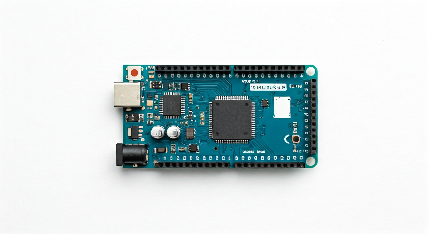
Released in 2015, the Arduino Zero represents a significant step forward for the Arduino platform, moving from 8-bit AVR microcontrollers to a more capable 32-bit ARM Cortex-M0+ architecture. This board is designed for makers, students, and embedded engineers who need more processing power, memory, and advanced peripherals than typically found on classic Arduino boards like the Uno. Its versatility makes it suitable for a wide range of applications, from complex sensor networks and data logging to robotics and audio processing.
At the heart of the Arduino Zero is the Atmel (now Microchip) SAMD21G18A microcontroller. This is a low-power, high-performance 32-bit microcontroller based on the ARM Cortex-M0+ core. It features a rich set of peripherals, including multiple timers, communication interfaces (UART, SPI, I2C), analog-to-digital converters (ADCs), and digital-to-analog converters (DACs). The SAMD21G18A also boasts 256KB of Flash memory for program storage and 32KB of SRAM for data, significantly more than its 8-bit predecessors.
The Arduino Zero sits in a unique position within the Arduino family. It's more powerful than the entry-level boards like the Arduino Uno or Nano, but less complex and often more power-efficient than higher-end boards like the Arduino Due or MKR series. It bridges the gap by offering a substantial upgrade in performance and features while maintaining the familiar Arduino programming environment and ease of use. This makes it an excellent choice for projects that are pushing the boundaries of what traditional Arduinos can handle, such as those involving more sophisticated algorithms, real-time data analysis, or the need for more program space.
This board is particularly well-suited for makers who are looking to transition from 8-bit microcontrollers to 32-bit ARM. Its extensive peripherals and ample memory allow for more complex software, including the potential for running real-time operating systems (RTOS) or more advanced libraries. Embedded engineers will appreciate the native USB capabilities, the efficient Cortex-M0+ core, and the array of communication options for interfacing with other devices or systems. Students can benefit from learning on a more modern architecture while still leveraging the vast Arduino ecosystem.
Watch
Related video, embedded from YouTube.
Specifications
| Microcontroller / SoC | Microchip SAMD21G18A |
| Architecture | 32-bit ARM Cortex-M0+ |
| Clock speed | 48 MHz |
| Flash / Storage | 256 KB |
| RAM / SRAM | 32 KB |
| Operating voltage | 3.3V |
| Digital I/O pins | 20 |
| Analog / ADC | 6 (12-bit resolution) |
| PWM | 11 (on most digital pins) |
| Connectivity | UART (Serial), SPI, I2C |
| USB | Native USB (Device and Host capable) |
| Power input | 7-12V recommended via VIN pin, 5V via USB or 5V pin |
| Dimensions | 75mm x 27mm |
Pinout & pin functions
| Pin | Function |
|---|---|
| GND | Ground |
| 3.3V | 3.3V Power Output |
| AREF | Analog Reference Input |
| A0 | Analog Input / Digital I/O |
| A1 | Analog Input / Digital I/O |
| A2 | Analog Input / Digital I/O |
| A3 | Analog Input / Digital I/O |
| A4 | Analog Input / Digital I/O, I2C SDA |
| A5 | Analog Input / Digital I/O, I2C SCL |
| D0 (RX) | Digital I/O, UART RX |
| D1 (TX) | Digital I/O, UART TX |
| D2 | Digital I/O |
| D3 | Digital I/O, PWM |
| D4 | Digital I/O |
| D5 | Digital I/O, PWM |
| D6 | Digital I/O, PWM |
| D7 | Digital I/O |
| D8 | Digital I/O |
| D9 | Digital I/O, PWM |
| D10 | Digital I/O, PWM, SPI MOSI |
| D11 | Digital I/O, PWM, SPI MISO |
| D12 | Digital I/O, SPI SCK |
| D13 | Digital I/O, SPI CS, LED (on-board) |
| D14 (SDA) | Digital I/O, I2C SDA |
| D15 (SCL) | Digital I/O, I2C SCL |
| VIN | Power Input (7-12V recommended) |
| 5V | 5V Power Output (regulated) |
| RESET | Reset Button |
| USB (Native) | USB Port for programming and communication |
Wiring & circuit basics
Powering the Arduino Zero requires attention to its operating voltage. The board operates at 3.3V logic levels, meaning any external components connected to its digital pins should also be 3.3V compatible. Connecting 5V components directly to digital pins can damage the SAMD21 microcontroller. Power can be supplied through the USB port (5V), the 5V pin (if a regulated 5V source is available), or the VIN pin, which accepts a wider voltage range (7-12V recommended) and is regulated down to 5V by an onboard regulator. Ensure your power supply can provide sufficient current, typically at least 500mA, especially when powering external devices or using the USB host functionality.
When interfacing with external sensors or modules, always verify their operating voltage and logic levels. For components that operate at 5V, a logic level converter is necessary to safely translate signals between the 3.3V of the Arduino Zero and the 5V of the component. For example, to connect a common 5V LED, you would connect its anode to a digital pin (e.g., D13) through a current-limiting resistor (around 220-330 ohms) and its cathode to GND. The Arduino Zero's onboard LED is also connected to D13.
For I2C communication, the Arduino Zero uses pins A4 (SDA) and A5 (SCL) for the primary I2C bus. If you are using a sensor that requires I2C, connect its SDA pin to A4 and its SCL pin to A5. Ensure the sensor shares a common ground with the Arduino Zero. Many I2C sensors also require pull-up resistors on the SDA and SCL lines; while some modules have these built-in, others may require external ones (typically 4.7k ohm to 3.3V). The Arduino IDE's Wire library simplifies I2C communication.
Programming & getting started
The Arduino Zero is primarily programmed using the Arduino IDE, which supports the SAMD architecture. After installing the appropriate board support package for the SAMD microcontrollers within the IDE, you can select 'Arduino Zero' from the board menu. Uploading code is typically done via the native USB port. Connect the Arduino Zero to your computer using a USB cable, select the correct COM port, and click the 'Upload' button. The board enters bootloader mode automatically when programmed, allowing for seamless flashing. For more advanced development, you can also use platforms like PlatformIO or explore MicroPython/CircuitPython, which offer alternative programming environments and languages.
To upload your first program, open the Arduino IDE, select 'File' > 'Examples' > '01.Basics' > 'Blink'. Choose 'Arduino Zero' from the 'Tools' > 'Board' menu and the correct COM port from the 'Tools' > 'Port' menu. Connect the Arduino Zero via USB. Click the Upload button (right arrow icon). The onboard LED (connected to D13) should start blinking. This simple sketch demonstrates basic digital output and confirms your programming setup is working correctly.