MakerLab Reference: ESP-01 (ESP8266) - The Tiny Wi-Fi Pioneer
Explore the foundational ESP-01 module, a compact and cost-effective way to add Wi-Fi connectivity to your projects using the ESP8266 SoC.
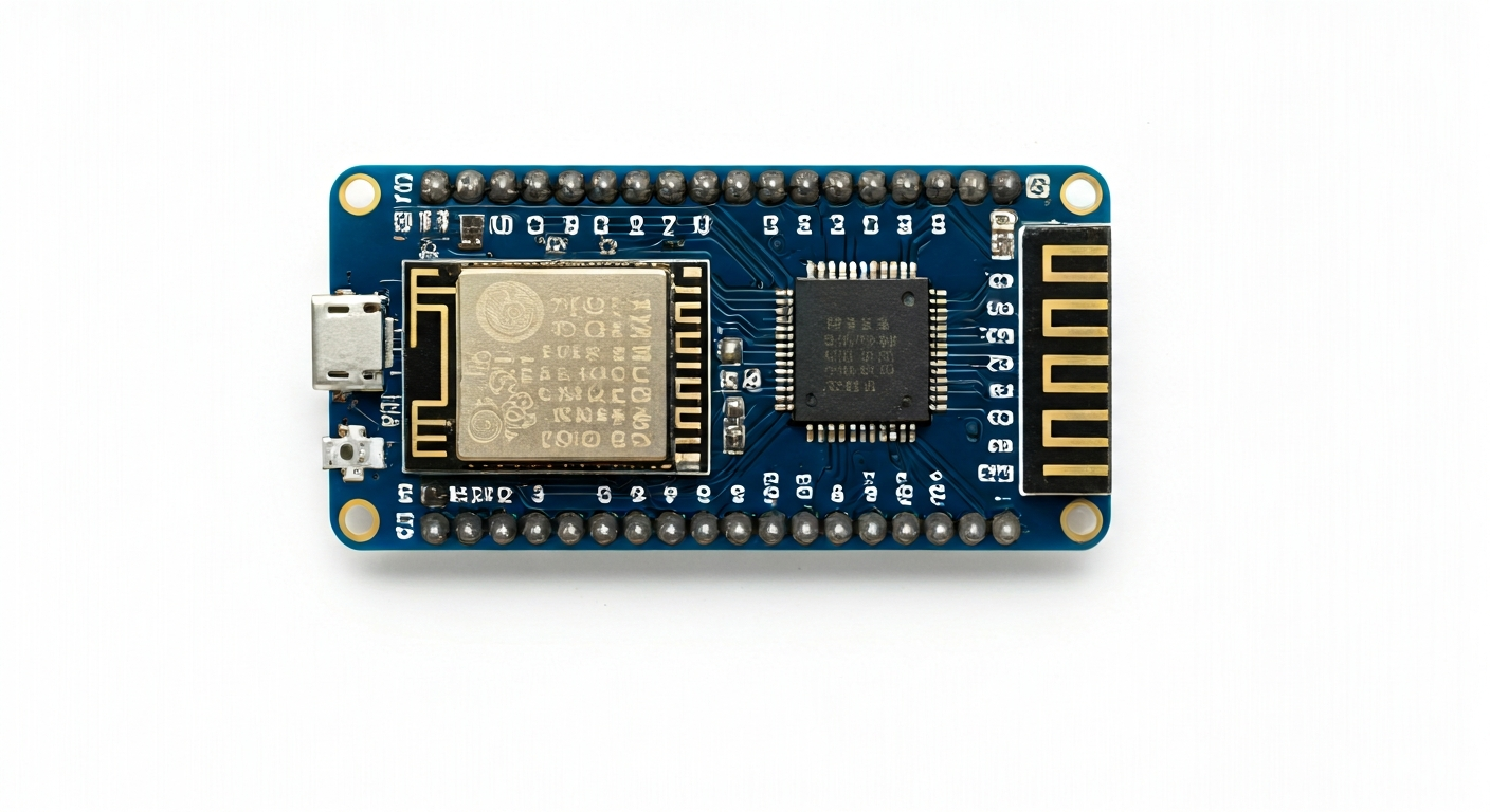
The ESP-01 is one of the earliest and most recognizable modules based on the ESP8266 Wi-Fi System-on-Chip (SoC). Released by Espressif Systems around 2014, it brought affordable Wi-Fi capabilities to the maker community, democratizing IoT development. This small, 8-pin module, often featuring a black PCB, is a direct gateway to the ESP8266's powerful networking features, making it ideal for simple connected devices and learning embedded networking.
At its heart, the ESP-01 utilizes the ESP8266EX chip, a highly integrated Wi-Fi microcontroller. The ESP8266 itself was a game-changer, offering TCP/IP networking stack and microcontroller functionality in a single, low-cost package. This allowed hobbyists and small businesses to create internet-connected devices without the need for a separate Wi-Fi module and a primary microcontroller, significantly reducing complexity and cost.
The ESP-01 module is a stripped-down implementation of the ESP8266, designed for minimal footprint and cost. It typically includes the ESP8266EX chip, an onboard flash memory chip (commonly 1MB or 4MB), and essential passive components. Its limited number of exposed pins means it's best suited for projects where Wi-Fi is the primary focus and I/O requirements are modest. It's a fantastic starting point for anyone looking to understand the fundamentals of embedded Wi-Fi communication and basic microcontroller programming.
While newer ESP boards like the ESP32 series offer more features (Bluetooth, more GPIO, faster processors), the ESP-01 remains relevant for its simplicity, extremely low cost, and the foundational knowledge it imparts about embedded Wi-Fi. It's perfect for makers who want to learn about AT command firmware, basic TCP/IP communication, or who need a tiny, cheap Wi-Fi interface for simple tasks like sensor data logging or remote control.
Watch
Related video, embedded from YouTube.
Specifications
| Microcontroller / SoC | ESP8266EX |
| Architecture | Tensilica L106 32-bit RISC Microprocessor |
| Clock speed | Typically 80 MHz (can be boosted to 160 MHz) |
| Flash / Storage | Typically 1MB or 4MB (onboard SPI flash) |
| RAM / SRAM | 32KB SRAM + 80KB XRAM (usable for code/data) |
| Operating voltage | 3.0V - 3.6V (3.3V recommended) |
| Digital I/O pins | 6 (exposed as GPIO0, GPIO2, GPIO4, GPIO5, GPIO12, GPIO13) |
| Analog / ADC | 1x 10-bit ADC (connected to GPIO A0) |
| PWM | Yes (Software PWM available on most GPIOs) |
| Connectivity | 802.11 b/g/n Wi-Fi (2.4 GHz) |
| USB | None (requires external programmer/adapter for flashing) |
| Power input | VCC (3.3V) and GND pins |
| Dimensions | Approx. 25mm x 14mm (excluding header pins) |
Pinout & pin functions
| Pin | Function |
|---|---|
| VCC | Power Input (3.3V) |
| GND | Ground |
| GPIO1 | UART TX (Serial Transmit) - Also used for flashing |
| GPIO3 | UART RX (Serial Receive) - Also used for flashing |
| GPIO2 | General Purpose Input/Output - Also boots in normal mode |
| GPIO0 | General Purpose Input/Output - Also boots in flash mode when LOW |
| GPIO4 | General Purpose Input/Output |
| GPIO5 | General Purpose Input/Output |
| CH_PD | Chip Enable / Power Down - Must be HIGH for operation (connect to VCC) |
| RST | Reset - Active LOW (can be pulled HIGH to VCC for normal operation) |
| GPIO12 | General Purpose Input/Output (MTDI) |
| GPIO13 | General Purpose Input/Output (MTDO) |
| ADC0 (GPIO17) | Analog-to-Digital Converter Input (connected to GPIO A0) |
Wiring & circuit basics
The ESP-01 operates at a strict 3.3V logic level. Connecting it directly to 5V components can damage the chip. Always use a level shifter or ensure that any connected components are 3.3V compatible. Powering the ESP-01 requires a stable 3.3V supply capable of providing at least 300mA, especially during Wi-Fi transmission. A common mistake is powering it from a weak 3.3V source, leading to brownouts and unreliable Wi-Fi connections. It is highly recommended to use an external 3.3V voltage regulator (like an AMS1117-3.3) if powering from a higher voltage source (e.g., 5V USB).
Ensure the CH_PD (Chip Enable/Power Down) pin is connected to VCC (3.3V) for the ESP8266 to operate. The RST (Reset) pin can be left floating or connected to VCC for normal operation; pulling it LOW will reset the chip. For programming, the GPIO0 pin needs to be pulled LOW during reset to enter bootloader mode, allowing firmware to be uploaded via the UART pins (GPIO1 TX, GPIO3 RX). A common setup for programming involves a momentary button connected to GPIO0 and ground, and another to RST and ground, alongside a USB-to-TTL serial adapter.
For a simple LED indicator project, connect an LED's anode to a GPIO pin (e.g., GPIO2) through a current-limiting resistor (typically 220-330 ohms) and the LED's cathode to GND. This allows you to turn the LED on and off by controlling the GPIO pin's state. For more complex sensors, like an I2C sensor (e.g., BMP180), you would connect the sensor's SDA pin to GPIO4 (or another available GPIO configured for I2C), its SCL pin to GPIO5 (or another I2C clock pin), its VCC to the ESP-01's VCC (3.3V), and its GND to the ESP-01's GND. Remember to check the sensor's specific voltage requirements and use level shifting if necessary.
Programming & getting started
The ESP-01 can be programmed using several toolchains. The most popular for beginners is the Arduino IDE, with the ESP8266 board support package installed. This allows you to write C++ code similar to standard Arduino sketches. Another option is MicroPython, offering a Python-based programming environment. For advanced users and direct hardware control, Espressif's ESP-IDF (IoT Development Framework) provides a comprehensive C/C++ SDK. Flashing firmware typically requires a USB-to-TTL serial adapter (e.g., FTDI or CH340 based) connected to the ESP-01's TX (GPIO1) and RX (GPIO3) pins, with GPIO0 pulled LOW during the initial power-up or reset to enter programming mode.
To upload your first sketch via the Arduino IDE: 1. Install the ESP8266 board package. 2. Connect a USB-to-TTL adapter to the ESP-01 (TX to RX, RX to TX, GND to GND). 3. Connect GPIO0 to GND (or use a button to ground it). 4. Connect VCC to 3.3V and CH_PD to 3.3V. 5. Power the adapter. 6. In the Arduino IDE, select the correct board (e.g., 'Generic ESP8266 Module'), COM port, and flash size. 7. Upload your sketch. 8. Disconnect GPIO0 from GND (or release the button) and reset the ESP-01 to run the program.