ESP32-C3-DevKitM-1: Your Gateway to RISC-V Wi-Fi and Bluetooth
A compact and affordable development board featuring Espressif's RISC-V based ESP32-C3 microcontroller for Wi-Fi and Bluetooth projects.
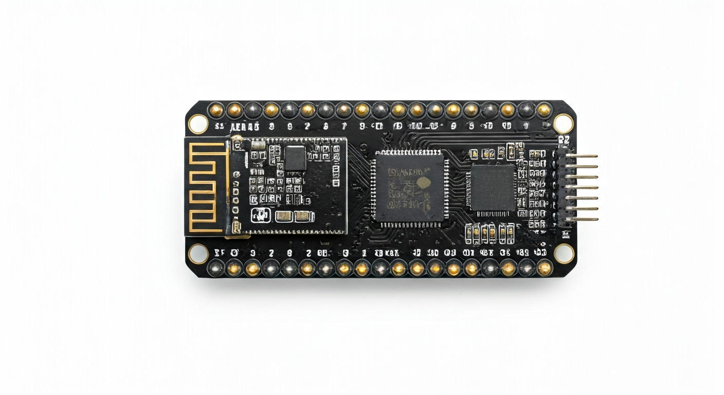
The ESP32-C3-DevKitM-1 is a popular development board designed by Espressif Systems, a company renowned for its low-cost, high-performance Wi-Fi and Bluetooth System-on-Chips (SoCs). This board serves as an accessible platform for makers, students, and embedded engineers to explore the capabilities of the ESP32-C3 chip. Its compact form factor and integrated USB interface make it exceptionally easy to get started with, requiring minimal external components for basic operation. The DevKitM-1 is particularly well-suited for IoT applications, smart home devices, and wearable technology due to its wireless connectivity and low power consumption.
At the heart of the ESP32-C3-DevKitM-1 is the ESP32-C3FN4 microcontroller. This chip represents a significant shift for Espressif, being their first RISC-V based SoC. It features a single-core 32-bit RISC-V processor running at up to 160 MHz, offering a good balance of performance and power efficiency. The ESP32-C3 also integrates Wi-Fi 4 (802.11 b/g/n) and Bluetooth 5 (LE) connectivity, making it a versatile choice for wireless communication. Unlike some of its predecessors in the ESP32 family, the ESP32-C3 does not natively support Bluetooth Classic, focusing instead on Bluetooth Low Energy for power-sensitive applications.
The ESP32-C3-DevKitM-1 sits within Espressif's extensive product line as a cost-effective entry point into RISC-V and modern wireless standards. It offers a compelling alternative to ARM-based microcontrollers for projects requiring built-in Wi-Fi and Bluetooth. Its history is tied to Espressif's strategy of diversifying its microcontroller offerings and embracing open-source architectures like RISC-V. This board is ideal for hobbyists looking to build their first connected device, students learning about embedded systems and wireless protocols, or engineers prototyping IoT solutions where cost and power efficiency are key considerations.
Watch
Related video, embedded from YouTube.
Specifications
| Microcontroller / SoC | ESP32-C3FN4 |
| Architecture | 32-bit RISC-V single-core processor |
| Clock speed | Up to 160 MHz |
| Flash / Storage | 4MB onboard SPI Flash |
| RAM / SRAM | 400KB SRAM (including 32KB RTC SRAM) |
| Operating voltage | 3.3V |
| Digital I/O pins | 22 (configurable) |
| Analog / ADC | 2x 12-bit SAR ADCs (shared with GPIOs) |
| PWM | Up to 6 channels (configurable) |
| Connectivity | Wi-Fi 4 (802.11 b/g/n), Bluetooth 5 (LE) |
| USB | USB-to-UART bridge (CH340C or similar) for programming and serial communication |
| Power input | 5V via USB or 5V/GND pins |
| Dimensions | 48.5mm x 24mm |
Pinout & pin functions
| Pin | Function |
|---|---|
| 3V3 | 3.3V Power Output |
| GND | Ground |
| EN | Enable/Reset Pin |
| IO0 | GPIO0 / Boot Mode Select |
| IO1 | GPIO1 / UART1 TX |
| IO2 | GPIO2 / ADC1 Channel 0 |
| IO3 | GPIO3 / UART1 RX |
| IO4 | GPIO4 / ADC2 Channel 4 |
| IO5 | GPIO5 / SPI2 SCK |
| IO6 | GPIO6 / SPI2 MISO |
| IO7 | GPIO7 / SPI2 MOSI |
| IO8 | GPIO8 / SPI2 CS |
| IO9 | GPIO9 / SPI2 CS |
| IO10 | GPIO10 / SPI2 SCK |
| IO11 | GPIO11 / SPI2 MISO |
| IO12 | GPIO12 / SPI2 MOSI |
| IO13 | GPIO13 / SPI2 CS |
| IO14 | GPIO14 / I2C0 SDA |
| IO15 | GPIO15 / I2C0 SCL |
| IO16 | GPIO16 / UART2 TX |
| IO17 | GPIO17 / UART2 RX |
| IO18 | GPIO18 / ADC1 Channel 1 |
| IO19 | GPIO19 / ADC1 Channel 2 |
| IO20 | GPIO20 / ADC1 Channel 3 |
| IO21 | GPIO21 / ADC2 Channel 0 |
| IO22 | GPIO22 / ADC2 Channel 1 |
| IO23 | GPIO23 / ADC2 Channel 2 |
| IO24 | GPIO24 / ADC2 Channel 3 |
| IO25 | GPIO25 / PWM Channel 0 |
| IO26 | GPIO26 / PWM Channel 1 |
| IO27 | GPIO27 / PWM Channel 2 |
| IO28 | GPIO28 / PWM Channel 3 |
| IO29 | GPIO29 / PWM Channel 4 |
| IO30 | GPIO30 / PWM Channel 5 |
| IO31 | GPIO31 / SPI3 SCK |
| IO32 | GPIO32 / SPI3 MISO |
| IO33 | GPIO33 / SPI3 MOSI |
| IO34 | GPIO34 / SPI3 CS |
| IO35 | GPIO35 / SPI3 CS |
| IO36 | GPIO36 / SPI3 SCK |
| IO37 | GPIO37 / SPI3 MISO |
| IO38 | GPIO38 / SPI3 MOSI |
| IO39 | GPIO39 / SPI3 CS |
| VP | Voltage Potential (ADC Input) |
| VN | Voltage Negative (ADC Input) |
| G32 | Ground (ADC Input) |
| G33 | Ground (ADC Input) |
| 5V | 5V Power Input |
| USB | USB Power Input |
Wiring & circuit basics
The ESP32-C3-DevKitM-1 operates at a logic level of 3.3V. Connecting 5V components directly to its GPIO pins can cause permanent damage. If you need to interface with 5V devices, use a logic level shifter or a voltage divider for input signals. Powering the board is straightforward: connect a 5V power source to the USB port or the 5V pin. The onboard voltage regulator will step this down to the 3.3V required by the ESP32-C3 chip and other components. Ensure your power supply can provide at least 500mA, especially when using Wi-Fi or Bluetooth, to avoid brownouts and unstable operation.
For a simple LED indicator, connect an LED's anode (longer leg) to a GPIO pin (e.g., GPIO25) through a current-limiting resistor (typically 220-330 ohms for standard LEDs). Connect the LED's cathode (shorter leg) to a GND pin. When the GPIO pin is HIGH (3.3V), the LED will illuminate. This setup is fundamental for understanding digital output and basic circuit construction.
To connect an I2C sensor, such as a BME280 environmental sensor, you will typically need to connect its VCC to a 3.3V pin, GND to a GND pin, SDA to the board's I2C SDA pin (e.g., GPIO14), and SCL to the board's I2C SCL pin (e.g., GPIO15). Always consult the sensor's datasheet for its specific voltage requirements and pinout. The ESP32-C3 supports I2C communication on multiple GPIO pins, offering flexibility in wiring.
Programming & getting started
The ESP32-C3-DevKitM-1 is well-supported by several popular development environments. For beginners and rapid prototyping, the Arduino IDE is an excellent choice. After installing the ESP32 board support package, you can select the ESP32-C3 Dev Module and upload code written in C/C++. MicroPython and CircuitPython also offer Python-based programming, providing a higher-level abstraction and faster development cycles. For advanced users and complex projects, Espressif's official ESP-IDF (Espressif IoT Development Framework) provides the most comprehensive control and features, typically used with C/C++ and tools like CMake.
To upload your first sketch (e.g., a Blink sketch) using the Arduino IDE: 1. Connect the ESP32-C3-DevKitM-1 to your computer via USB. 2. Open the Arduino IDE. 3. Go to Tools > Board > ESP32 and select 'ESP32C3 Dev Module'. 4. Select the correct COM port under Tools > Port. 5. Paste the Blink sketch code into the editor. 6. Click the Upload button. The board will automatically enter bootloader mode for flashing. You should see the onboard LED (usually connected to GPIO2) blinking.