ESP32-DevKitC: Your Gateway to Powerful IoT Development
The ESP32-DevKitC is a versatile development board featuring Espressif's flagship ESP32 chip, ideal for Wi-Fi and Bluetooth enabled projects.
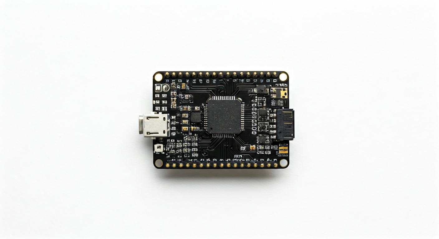
The ESP32-DevKitC is a popular and accessible development board designed by Espressif Systems, serving as an excellent platform for prototyping and developing applications with the ESP32 System-on-Chip (SoC). It breaks out most of the ESP32's GPIO pins to standard 0.1-inch pitch headers, making it easy to connect external components and sensors. The board typically includes a USB-to-UART bridge for easy programming and serial communication directly from a computer.
At its heart lies the ESP32, a highly integrated Wi-Fi and Bluetooth SoC. This chip features a dual-core Tensilica LX6 microprocessor, running at up to 240 MHz, and includes built-in antennas for Wi-Fi and Bluetooth 4.2 (or later, depending on the specific ESP32 variant used on the board). It boasts a rich set of peripherals, including ADCs, DACs, I2C, SPI, UART, CAN, and PWM controllers, making it suitable for a wide range of embedded applications.
The ESP32-DevKitC represents a significant step up in performance and features compared to its predecessor, the ESP8266. While the ESP8266 offered Wi-Fi connectivity and a single core, the ESP32 adds Bluetooth, dual cores, more GPIOs, and enhanced analog capabilities. This makes the ESP32-DevKitC particularly appealing to makers, students, and engineers looking to build more complex, connected projects that require both wireless communication and substantial processing power, such as IoT devices, smart home controllers, and data loggers.
Initially released around 2017, the ESP32-DevKitC has become a de facto standard for ESP32 development. Its widespread adoption, extensive community support, and the availability of numerous libraries and examples have cemented its position as a go-to board for hobbyists and professionals alike. Its ease of use, combined with the powerful capabilities of the ESP32, makes it an excellent choice for anyone venturing into the world of embedded systems and the Internet of Things.
Specifications
| Microcontroller / SoC | Espressif ESP32-WROOM-32 (or similar ESP32 module) |
| Architecture | Dual-core Tensilica LX6 microprocessor |
| Clock speed | Up to 240 MHz |
| Flash / Storage | 4MB (on-module, typically) |
| RAM / SRAM | 520 KB SRAM |
| Operating voltage | 3.3V |
| Digital I/O pins | 36 (available on module, exposed pins vary by board revision) |
| Analog / ADC | 12-bit SAR ADC (up to 18 channels) |
| PWM | Up to 16 channels |
| Connectivity | Wi-Fi 802.11 b/g/n, Bluetooth v4.2 BR/EDR and BLE |
| USB | Micro-USB for power and programming (via CP2102 or CH340 USB-to-UART bridge) |
| Power input | 5V via Micro-USB, or 5V/VIN pin, or 3.3V pin |
| Dimensions | Approx. 52mm x 26.5mm |
Pinout & pin functions
| Pin | Function |
|---|---|
| 3V3 | 3.3V power output |
| EN | Enable pin (active high; pull low to reset) |
| VP / GPIO34 | ADC1 Channel 6, Input only |
| VN / GPIO35 | ADC1 Channel 7, Input only |
| GND | Ground |
| G32 / GPIO32 | Input/Output, ADC1 Channel 4 |
| G33 / GPIO33 | Input/Output, ADC1 Channel 5 |
| G25 / GPIO25 | Input/Output, DAC1, ADC1 Channel 8 |
| G26 / GPIO26 | Input/Output, ADC1 Channel 9 |
| G27 / GPIO27 | Input/Output, ADC1 Channel 10 |
| G14 / GPIO14 | Input/Output, HSPI MISO |
| G12 / GPIO12 | Input/Output, HSPI MISO, ADC1 Channel 12 |
| G13 / GPIO13 | Input/Output, HSPI MOSI, ADC1 Channel 11 |
| G2 / GPIO2 | Input/Output, ADC1 Channel 2 |
| G4 / GPIO4 | Input/Output, ADC1 Channel 3 |
| G15 / GPIO15 | Input/Output, HSPI SCK, ADC1 Channel 13 |
| G5 / GPIO5 | Input/Output, HSPI CS |
| G18 / GPIO18 | Input/Output, I2S0 TX_BCLK, ADC1 Channel 0 |
| G19 / GPIO19 | Input/Output, I2S0 TX_WS, I2C SCL |
| G21 / GPIO21 | Input/Output, I2S0 RX_SCLK, I2C SDA |
| G22 / GPIO22 | Input/Output, I2S0 RX_WS, ADC1 Channel 1 |
| G17 / GPIO17 | Input/Output, I2S0 RX_SD |
| G16 / GPIO16 | Input/Output, I2S0 TX_SD |
| TXD0 / GPIO1 | UART0 TXD |
| RXD0 / GPIO3 | UART0 RXD, ADC1 Channel 0 |
| G0 / GPIO0 | Input/Output, Boot button |
| G2 / GPIO2 | Input/Output, ADC1 Channel 2 |
| G15 / GPIO15 | Input/Output, HSPI SCK, ADC1 Channel 13 |
| G4 / GPIO4 | Input/Output, ADC1 Channel 3 |
| G5 / GPIO5 | Input/Output, HSPI CS |
| G12 / GPIO12 | Input/Output, HSPI MISO, ADC1 Channel 12 |
| G13 / GPIO13 | Input/Output, HSPI MOSI, ADC1 Channel 11 |
| G14 / GPIO14 | Input/Output, HSPI MISO |
| G27 / GPIO27 | Input/Output, ADC1 Channel 10 |
| G26 / GPIO26 | Input/Output, ADC1 Channel 9 |
| G25 / GPIO25 | Input/Output, DAC1, ADC1 Channel 8 |
| G33 / GPIO33 | Input/Output, ADC1 Channel 5 |
| G32 / GPIO32 | Input/Output, ADC1 Channel 4 |
| G35 / GPIO35 | Input only, ADC1 Channel 7 |
| G34 / GPIO34 | Input only, ADC1 Channel 6 |
| G39 / GPIO39 | Input only, ADC1 Channel 3 |
| G36 / GPIO36 | Input only, ADC1 Channel 0 |
| G37 / GPIO37 | Input only, ADC1 Channel 1 |
| G38 / GPIO38 | Input only, ADC1 Channel 2 |
| VIN | 5V input |
| GND | Ground |
| 3V3 | 3.3V power output |
| USB | Micro-USB connector (5V power and data) |
Wiring & circuit basics
The ESP32-DevKitC operates at a logic level of 3.3V. Connecting 5V signals directly to its GPIO pins can damage the microcontroller. Always use a level shifter if interfacing with 5V components. Powering the board can be done via the Micro-USB port (typically 5V at 500mA or more) or the VIN pin. The board has an onboard 3.3V voltage regulator that can supply up to 500mA, but it's advisable to keep total current draw below this to avoid overheating, especially when powering external devices.
A common beginner project is to blink an LED. Connect an LED's anode (longer leg) to a digital GPIO pin (e.g., GPIO2) and its cathode (shorter leg) through a current-limiting resistor (typically 220-330 ohms for a standard LED) to a GND pin. This setup ensures the LED receives the correct voltage and current, preventing damage to both the LED and the ESP32.
For more advanced projects, consider connecting I2C sensors. For example, to connect a BME280 sensor, use 3.3V from the 3V3 pin to the sensor's VCC, GND to a GND pin, and the sensor's SDA and SCL pins to the ESP32's designated I2C pins (GPIO21 for SDA and GPIO19 for SCL). Ensure your code is configured to use these specific pins for I2C communication.
Programming & getting started
The ESP32-DevKitC is well-supported by multiple development environments. For beginners, the Arduino IDE with the ESP32 board manager installed is a popular choice, offering a familiar C++ based programming environment. MicroPython and CircuitPython also provide Python-based alternatives for rapid prototyping. For professional embedded development, Espressif's own ESP-IDF (IoT Development Framework) offers the most comprehensive features and control, while PlatformIO is a versatile IDE extension supporting various frameworks including Arduino and ESP-IDF.
To upload your first program using the Arduino IDE: 1. Install the ESP32 board support via the Boards Manager. 2. Select the correct ESP32 Dev Module from the Tools > Board menu. 3. Connect the ESP32-DevKitC to your computer via USB. 4. Choose the correct COM port from the Tools > Port menu. 5. Write or load a sketch (e.g., the Blink example). 6. Click the Upload button. The board will typically enter bootloader mode automatically, or you may need to press the BOOT button while pressing and releasing the RESET button.