ESP32-H2: The Low-Power, Thread-Ready MCU for IoT
Espressif's compact and energy-efficient microcontroller designed for smart home devices and low-power wireless applications.
The ESP32-H2 is a powerful, low-power microcontroller from Espressif Systems, a prominent player in the IoT semiconductor market. It is part of the ESP32 family, known for its integrated Wi-Fi and Bluetooth capabilities. However, the ESP32-H2 distinguishes itself by focusing on Thread and Bluetooth Low Energy (BLE) connectivity, making it ideal for applications where power efficiency and mesh networking are paramount. It's designed to be a cost-effective and compact solution for a wide range of smart home devices, industrial sensors, and wearable technology.
At the heart of the ESP32-H2 is Espressif's proprietary RISC-V 32-bit single-core processor, operating at up to 96 MHz. This architecture offers a good balance of performance and energy efficiency. Unlike some of its ESP32 siblings, the ESP32-H2 does not feature Wi-Fi but excels in its support for 802.15.4, which is the foundational radio standard for Thread and Zigbee. This strategic design choice positions the ESP32-H2 as a go-to chip for building robust and interoperable smart home ecosystems, particularly those leveraging the Matter standard.
Released around 2023, the ESP32-H2 represents Espressif's commitment to expanding its portfolio for the evolving IoT landscape. Its predecessor, the ESP32, was widely adopted for its versatility. The ESP32-H2 builds upon this legacy by offering enhanced security features, improved power management, and specialized wireless protocols. It is particularly suited for makers and engineers looking to develop battery-powered devices, remote sensing nodes, or smart lighting systems that can benefit from the low-power, mesh networking capabilities of Thread and BLE.
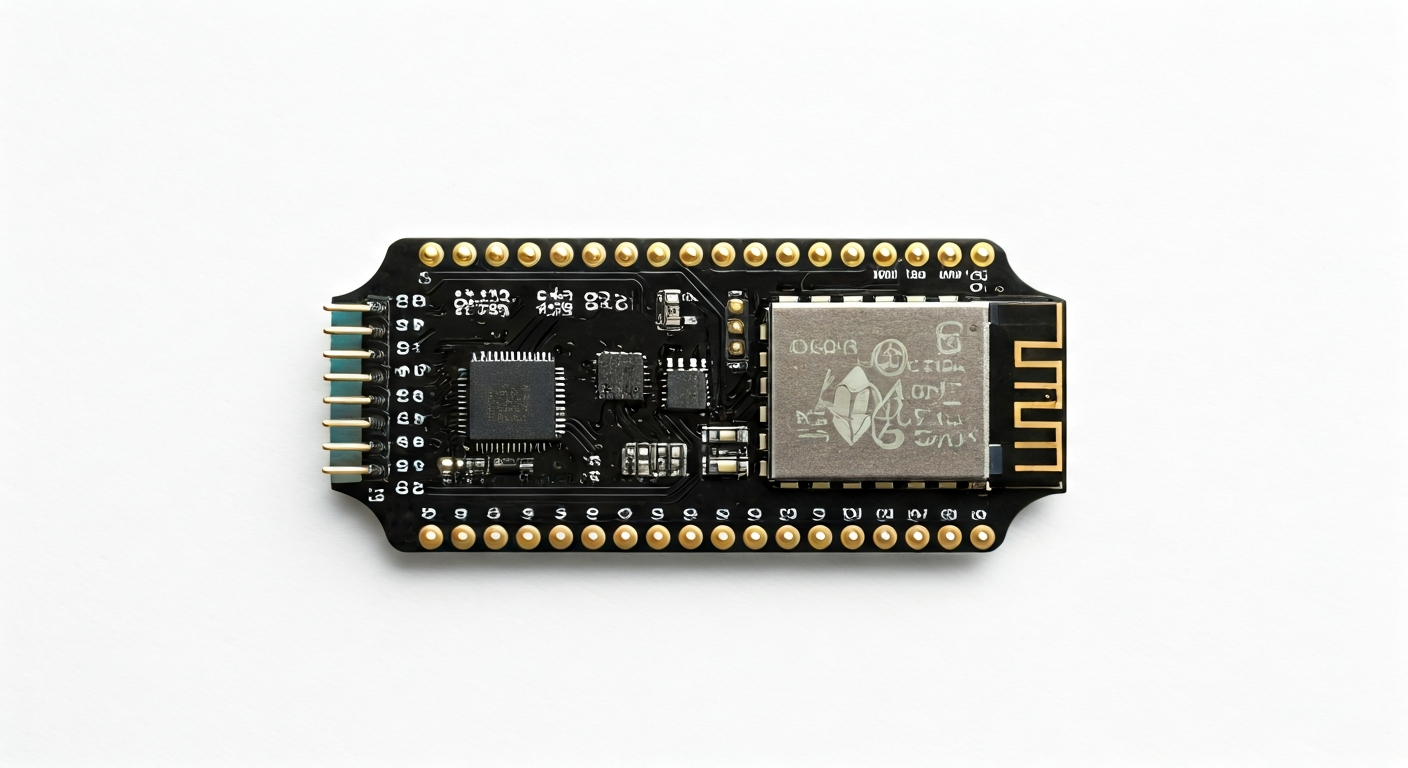
The ESP32-H2 is typically found on development boards that are breadboard-friendly and feature essential components like a USB-to-serial converter for easy programming, a voltage regulator, and accessible pin headers. These boards are designed to simplify the prototyping process, allowing users to quickly experiment with the chip's capabilities without complex external circuitry. Whether you are a student learning about embedded systems, a hobbyist building a smart home project, or an engineer designing a commercial product, the ESP32-H2 offers a compelling combination of features, performance, and power efficiency.
Watch
Related video, embedded from YouTube.
Specifications
| Microcontroller / SoC | ESP32-H2 |
| Architecture | RISC-V 32-bit single-core processor |
| Clock speed | Up to 96 MHz |
| Flash / Storage | Typically 4MB to 16MB external SPI Flash (on development boards) |
| RAM / SRAM | 16KB of SRAM, 32KB of RTC SRAM |
| Operating voltage | 3.3V |
| Digital I/O pins | Up to 23 GPIOs (varies by board implementation) |
| Analog / ADC | Up to 5 ADC channels (12-bit resolution) |
| PWM | Up to 16 channels (general purpose timer/PWM) |
| Connectivity | Bluetooth 5 (LE), IEEE 802.15.4 (Thread, Zigbee) |
| USB | USB-to-serial converter (on most dev boards, e.g., CH340, CP210x) for programming and serial communication |
| Power input | Typically 5V via USB or VIN pin; 3.3V regulator on board |
| Dimensions | Varies by development board, but the ESP32-H2 module itself is very compact |
Pinout & pin functions
| Pin | Function |
|---|---|
| 3V3 | 3.3V Power Output |
| GND | Ground |
| GPIO0 | General Purpose Input/Output; Boot mode selection (low during boot) |
| GPIO1 (TXD0) | General Purpose Input/Output; UART0 Transmit |
| GPIO2 (RXD0) | General Purpose Input/Output; UART0 Receive |
| GPIO3 | General Purpose Input/Output |
| GPIO4 | General Purpose Input/Output |
| GPIO5 | General Purpose Input/Output |
| GPIO6 | General Purpose Input/Output |
| GPIO7 | General Purpose Input/Output |
| GPIO8 | General Purpose Input/Output |
| GPIO9 | General Purpose Input/Output |
| GPIO10 | General Purpose Input/Output |
| GPIO11 | General Purpose Input/Output |
| GPIO12 | General Purpose Input/Output; ADC2_CH0 |
| GPIO13 | General Purpose Input/Output; ADC2_CH1 |
| GPIO14 | General Purpose Input/Output; ADC2_CH2 |
| GPIO15 | General Purpose Input/Output; ADC2_CH3 |
| GPIO16 | General Purpose Input/Output; ADC2_CH4 |
| GPIO17 | General Purpose Input/Output; ADC1_CH0 |
| GPIO18 | General Purpose Input/Output; ADC1_CH1 |
| GPIO19 | General Purpose Input/Output; ADC1_CH2 |
| GPIO20 | General Purpose Input/Output; ADC1_CH3 |
| GPIO21 | General Purpose Input/Output; ADC1_CH4 |
| GPIO22 | General Purpose Input/Output |
| GPIO23 | General Purpose Input/Output |
| GPIO24 | General Purpose Input/Output |
| GPIO25 | General Purpose Input/Output |
| GPIO26 | General Purpose Input/Output |
| GPIO27 | General Purpose Input/Output |
| GPIO28 | General Purpose Input/Output |
| GPIO29 | General Purpose Input/Output |
| GPIO30 | General Purpose Input/Output |
| GPIO31 | General Purpose Input/Output |
| EN | Enable Pin (Active High) |
| RST | Reset Pin (Active Low) |
| VIN | External Power Input (typically 5V) |
| USB D+ / D- | USB Data lines (for programming and serial communication) |
Wiring & circuit basics
Powering the ESP32-H2 development board is straightforward. Most boards are designed to be powered via a 5V USB connection, which is then regulated down to the 3.3V required by the ESP32-H2 chip. You can also power the board through the VIN pin, which should be connected to a stable 5V source. Ensure that your power supply can provide at least 500mA, especially if the ESP32-H2 will be transmitting wirelessly, as current draw can spike during these operations. Avoid powering the board directly with 5V through the 3V3 pin, as this can damage the onboard regulator and the chip.
The ESP32-H2 operates at a logic level of 3.3V. This means that any sensors, LEDs, or other peripherals you connect to its GPIO pins must also be compatible with 3.3V logic. Connecting a 5V device directly to a GPIO pin can cause damage. If you need to interface with 5V devices, you will need a logic level shifter. For example, to safely connect an LED, you would connect a GPIO pin to one end of a current-limiting resistor (e.g., 220-330 ohms), and the other end of the resistor to the LED's anode. The LED's cathode would then be connected to a GND pin on the ESP32-H2.
For an I2C communication example, you would connect the SDA (Serial Data) pin of your I2C sensor to a designated I2C SDA pin on the ESP32-H2 (often GPIO21 or GPIO13, depending on the board and configuration). The SCL (Serial Clock) pin of the sensor connects to the corresponding I2C SCL pin on the ESP32-H2 (often GPIO22 or GPIO14). Both the sensor and the ESP32-H2 need to share a common ground connection. Remember that I2C typically requires pull-up resistors on both SDA and SCL lines, which are often included on development boards or can be added externally.
Programming & getting started
The ESP32-H2 can be programmed using several popular development environments. The Arduino IDE is a common choice, offering a familiar C++ based programming environment with extensive libraries. To use it, you'll need to install the ESP32 board support package via the Board Manager. MicroPython and CircuitPython are also excellent options for rapid prototyping, providing a Pythonic interface to the hardware. For more advanced users and professional development, Espressif's official ESP-IDF (Espressif IoT Development Framework) offers the most control and access to the chip's full capabilities, often used with PlatformIO or directly via command-line tools.
To upload your first program (often called 'sketch' in Arduino IDE or 'script' in MicroPython/CircuitPython) to the ESP32-H2, connect the board to your computer via USB. In the Arduino IDE, select the correct board (e.g., 'ESP32-H2 Dev Module') and COM port. Write a simple 'Blink' sketch, which blinks an onboard LED, and click the upload button. The IDE will compile the code and flash it to the microcontroller. For MicroPython/CircuitPython, you'll typically need to flash the interpreter firmware first, then use a tool like Thonny IDE or ampy to upload your Python scripts.