ESP32-S3-DevKitC-1: Your Gateway to Advanced IoT Projects
A versatile development board featuring Espressif's powerful ESP32-S3 SoC, ideal for AIoT applications and complex embedded projects.
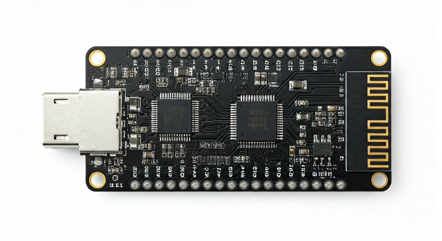
The ESP32-S3-DevKitC-1 is a popular development board designed by Espressif Systems, serving as an excellent platform for prototyping and developing a wide range of IoT and embedded applications. It is built around the ESP32-S3 System-on-Chip (SoC), a significant upgrade over previous ESP32 generations, offering enhanced performance, expanded memory, and advanced features like AI acceleration.
At its core, the ESP32-S3 SoC is a dual-core Xtensa LX7 microprocessor running at up to 240 MHz. It integrates Wi-Fi 4 (802.11 b/g/n) and Bluetooth 5 (LE) connectivity, making it ideal for wireless communication. The S3 variant is particularly notable for its inclusion of vector instructions that accelerate neural network and signal processing workloads, positioning it as a strong contender for edge AI applications. It also features a rich set of peripherals, including GPIOs, ADCs, DACs, SPI, I2C, UART, and USB OTG.
Compared to its predecessors like the ESP32 and ESP32-S2, the ESP32-S3 offers a more powerful CPU, more SRAM, and crucially, the AI acceleration capabilities. This makes it suitable for makers and engineers looking to push the boundaries of what's possible with low-cost microcontrollers, such as on-device machine learning inference, advanced sensor fusion, and complex real-time control systems. The DevKitC-1 form factor is designed for ease of use, with accessible pins and onboard USB-to-serial conversion.
This board is well-suited for hobbyists, students, and professional engineers who need a robust and feature-rich platform for IoT projects, smart home devices, robotics, wearable technology, and even basic AI-powered applications. Its extensive peripheral set and powerful processing capabilities allow for sophisticated projects that might have previously required more expensive or complex hardware.
Watch
Related video, embedded from YouTube.
Specifications
| Microcontroller / SoC | Espressif ESP32-S3-WROOM-1 (or similar module with ESP32-S3 chip) |
| Architecture | Dual-core Xtensa LX7 microprocessor |
| Clock speed | Up to 240 MHz |
| Flash / Storage | Typically 4MB or 8MB onboard SPI Flash (variant dependent) |
| RAM / SRAM | 512 KB SRAM |
| Operating voltage | 3.3V |
| Digital I/O pins | 34 (configurable) |
| Analog / ADC | 14x 12-bit SAR ADCs |
| PWM | 15 channels |
| Connectivity | Wi-Fi 802.11 b/g/n, Bluetooth 5 (LE) |
| USB | USB Type-C for power and programming (via USB-to-serial chip) |
| Power input | USB Type-C (5V), 2-pin header (3.3V-5V) |
| Dimensions | 75mm x 30mm (approximate) |
Pinout & pin functions
| Pin | Function |
|---|---|
| 3V3 | 3.3V Power Output |
| GND | Ground |
| EN | Enable (Reset) |
| IO0 | Boot Mode Select (Low during reset enters download mode) |
| IO1 (TX0) | UART0 Transmit |
| IO2 | General Purpose I/O, ADC1_CH2 |
| IO3 | General Purpose I/O, ADC1_CH3 |
| IO4 | General Purpose I/O, ADC1_CH4 |
| IO5 | General Purpose I/O, SPI2 SCK |
| IO6 | General Purpose I/O, SPI2 MOSI |
| IO7 | General Purpose I/O, SPI2 MISO |
| IO8 | General Purpose I/O, SPI2 CS0 |
| IO9 | General Purpose I/O, ADC1_CH12 |
| IO10 | General Purpose I/O, ADC1_CH13 |
| IO11 | General Purpose I/O, ADC1_CH14 |
| IO12 | General Purpose I/O, ADC1_CH15 |
| IO13 | General Purpose I/O, SPI2 MOSI |
| IO14 | General Purpose I/O, SPI2 MISO |
| IO15 | General Purpose I/O, SPI2 SCK |
| IO16 | General Purpose I/O, SPI2 CS0 |
| IO17 | General Purpose I/O, ADC1_CH17 |
| IO18 | General Purpose I/O, ADC1_CH18 |
| IO19 | General Purpose I/O, ADC1_CH19 |
| IO20 | General Purpose I/O, ADC1_CH20 |
| IO21 | General Purpose I/O, ADC1_CH21 |
| IO26 | General Purpose I/O, DAC_1, ADC1_CH26 |
| IO27 | General Purpose I/O, DAC_2, ADC1_CH27 |
| IO28 | General Purpose I/O, ADC1_CH28 |
| IO29 | General Purpose I/O, ADC1_CH29 |
| IO30 | General Purpose I/O, ADC1_CH30 |
| IO31 | General Purpose I/O, ADC1_CH31 |
| IO32 | General Purpose I/O, ADC1_CH1 |
| IO33 | General Purpose I/O, ADC1_CH0 |
| IO34 | General Purpose I/O, ADC1_CH4 |
| IO35 | General Purpose I/O, ADC1_CH5 |
| IO36 | General Purpose I/O, ADC1_CH6 |
| IO37 | General Purpose I/O, ADC1_CH7 |
| IO38 | General Purpose I/O, ADC2_CH0 |
| IO39 | General Purpose I/O, ADC2_CH1 |
| USB D+ / IO40 | USB D+ (used for USB OTG) |
| USB D- / IO41 | USB D- (used for USB OTG) |
| IO42 | General Purpose I/O |
| IO43 | General Purpose I/O |
| IO44 | General Purpose I/O |
| IO45 | General Purpose I/O |
| IO46 | General Purpose I/O |
Wiring & circuit basics
The ESP32-S3-DevKitC-1 operates at a logic level of 3.3V. It's crucial to use 3.3V-compatible components or level shifters when interfacing with 5V devices. Powering the board can be done via the USB Type-C port, which supplies 5V. Alternatively, a 5V or 3.3V supply can be connected to the VIN pin on the 2-pin header, and the board's onboard regulator will step it down to 3.3V for the SoC and peripherals. Avoid supplying more than 5V to the VIN pin. Ensure the power source can provide at least 500mA, especially when using Wi-Fi or Bluetooth, to prevent brownouts.
When connecting external components, always connect them to the 3.3V pins or the VIN pin as appropriate. For example, to control an LED, connect one leg of the LED to a GPIO pin (e.g., IO23) and the other leg through a current-limiting resistor (typically 220-330 ohms) to GND. The GPIO pin will then toggle between 3.3V (HIGH) and 0V (LOW) to turn the LED on and off. This resistor prevents excessive current from flowing through the LED and the GPIO pin, protecting both.
For I2C communication, use the designated SDA and SCL pins. On the ESP32-S3-DevKitC-1, these are typically mapped to IO33 (SDA) and IO34 (SCL), though other GPIOs can be configured. Connect the VCC pin of the I2C sensor to the board's 3.3V pin, GND to GND, SDA to IO33, and SCL to IO34. Remember that I2C devices often require pull-up resistors on the SDA and SCL lines, which are sometimes included on the sensor module itself or may need to be added externally (e.g., 4.7k Ohm resistors to 3.3V).
Programming & getting started
The ESP32-S3-DevKitC-1 is well-supported by various development environments. The most common is the Arduino IDE, which requires installing the ESP32 board package via the Board Manager. This allows you to program the ESP32-S3 using familiar Arduino C++ syntax. For more advanced users or specific applications, Espressif's official ESP-IDF (Espressif IoT Development Framework) provides a comprehensive C/C++ SDK with extensive documentation and examples. MicroPython and CircuitPython are also excellent choices for rapid prototyping, offering a Python-based programming experience.
To upload your first sketch using the Arduino IDE: 1. Ensure the ESP32 board package is installed. 2. Select the correct board (e.g., 'ESP32-S3 Dev Module'). 3. Connect the ESP32-S3-DevKitC-1 to your computer via USB. 4. Select the correct COM port. 5. Press the 'BOOT' button on the board and hold it while clicking the 'RESET' button, then release 'RESET' and then 'BOOT' to enter download mode if the upload fails initially (this is often automatic). 6. Click the 'Upload' button in the IDE. The board will compile the code and flash it.