ESP32 (WROOM-32): Your Gateway to Advanced IoT Projects
The ESP32 WROOM-32 is a versatile and powerful microcontroller module ideal for ambitious makers and embedded engineers venturing into IoT.
The ESP32 WROOM-32 is a highly integrated Wi-Fi and Bluetooth System-on-Chip (SoC) module developed by Espressif Systems. It's the successor to the popular ESP8266 and represents a significant leap in performance, features, and connectivity options. This module is designed for a wide range of applications, from smart home devices and industrial automation to wearable technology and complex sensor networks. Its dual-core processor, abundant peripherals, and low power consumption make it a compelling choice for projects requiring both robust processing power and wireless communication.
At the heart of the ESP32 WROOM-32 is the ESP32-D0WDQ6 chip, which features two Xtensa LX6 cores running at up to 240MHz. This dual-core architecture allows for efficient multitasking, enabling one core to handle demanding tasks like signal processing or machine learning inference while the other manages real-time operations and connectivity. The chip also boasts a rich set of integrated peripherals, including a wide array of GPIO pins, analog-to-digital converters (ADCs), digital-to-analog converters (DACs), touch sensors, SPI, I2C, UART, CAN, and Ethernet MAC interfaces, alongside a powerful hardware cryptographic accelerator.
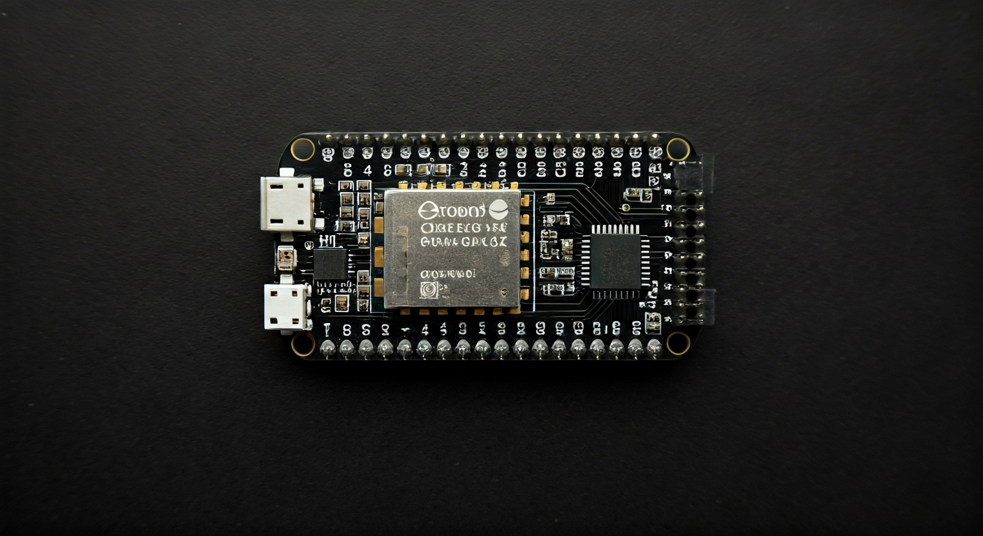
The WROOM-32 is one of the most popular form factors for the ESP32 family, featuring an integrated PCB antenna, making it easier to integrate into designs without the need for external RF components. It comes with 4MB of SPI flash memory for program storage and configuration. This module is particularly well-suited for makers and engineers who need more than just basic Wi-Fi connectivity. Its advanced features, such as Bluetooth Low Energy (BLE) support, deep sleep modes for power efficiency, and the ability to handle complex communication protocols, open doors to sophisticated IoT applications that were previously out of reach for hobbyist-grade hardware.
Released around 2016, the ESP32 quickly established itself as a favorite among the maker community due to its impressive feature set at an affordable price point. It bridges the gap between low-cost microcontrollers like the ESP8266 and more powerful, expensive embedded systems. Whether you're building a smart thermostat, a remote sensor array, a voice-controlled assistant, or a custom robotics platform, the ESP32 WROOM-32 provides the processing power, connectivity, and flexibility to bring your ideas to life.
Specifications
| Microcontroller / SoC | Espressif ESP32-D0WDQ6 |
| Architecture | Dual-core Xtensa LX6 |
| Clock speed | Up to 240 MHz |
| Flash / Storage | 4MB SPI Flash (on-board) |
| RAM / SRAM | 520 KB SRAM |
| Operating voltage | 3.0V - 3.6V (module operates at 3.3V) |
| Digital I/O pins | Up to 34 GPIO |
| Analog / ADC | 12-bit SAR ADCs (up to 18 channels) |
| PWM | Up to 16 channels (timers) |
| Connectivity | Wi-Fi 802.11 b/g/n, Bluetooth v4.2 BR/EDR and BLE |
| USB | None on the module itself (requires external USB-to-UART converter for programming) |
| Power input | Typically 5V via micro-USB (on development boards), or 3.3V direct supply |
| Dimensions | 24.0mm x 16.0mm x 3.2mm (module) |
Pinout & pin functions
| Pin | Function |
|---|---|
| 3V3 | 3.3V Power Output |
| GND | Ground |
| EN | Enable Pin (High to enable) |
| GPIO34 | Input only, ADC1_CH6 |
| GPIO35 | Input only, ADC1_CH7 |
| GPIO36 | Input only, ADC1_CH0 |
| GPIO39 | Input only, ADC1_CH3 |
| GPIO32 | ADC1_CH4, Touch0 |
| GPIO33 | ADC1_CH2, Touch1 |
| GPIO25 | DAC1, ADC1_CH8, ADC2_CH8 |
| GPIO26 | DAC2, ADC1_CH9, ADC2_CH9 |
| GPIO27 | ADC1_CH5, ADC2_CH7, Touch2 |
| GPIO14 | HSPI_MISO, Touch3 |
| GPIO12 | HSPI_MISO, MTDI, ADC1_CH5 |
| GPIO13 | HSPI_MOSI, MTDO, ADC1_CH4 |
| GPIO15 | HSPI_CLK, MTCK, ADC1_CH3 |
| GPIO2 | ADC2_CH4, Touch4 |
| GPIO4 | ADC2_CH0, Touch5 |
| GPIO0 | Boot Pin (Low during boot for flash mode), Touch6 |
| GPIO21 | I2C SDA |
| GPIO22 | I2C SCL |
| GPIO19 | I2S0_RXD, MISO, U1RXD |
| GPIO23 | I2S0_TXD, MOSI, U1TXD |
| GPIO18 | I2S0_CLK, SCK, U1RTS |
| GPIO5 | HSPI_CS0, U1CTS |
| GPIO17 | HSPI_CS1 |
| GPIO16 | U0RXD |
| GPIO15 | U0TXD |
| GPIO4 | ADC2_CH0, Touch5 |
| GPIO2 | ADC2_CH4, Touch4 |
| GPIO15 | MTDI, HSPI_CLK, ADC1_CH3 |
| GPIO2 | ADC2_CH4, Touch4 |
| GPIO0 | Boot Pin, Touch6 |
| GPIO1 | U0TXD |
| GPIO3 | U0RXD |
Wiring & circuit basics
The ESP32 WROOM-32 module operates at 3.3V. While most development boards include a voltage regulator to accept 5V input (often via micro-USB) and step it down to 3.3V, it's crucial to ensure you do not apply voltages higher than 3.6V directly to the module's 3.3V pin. Connecting 5V directly to a 3.3V pin will likely damage the chip. When interfacing with external components, remember that the ESP32's GPIO pins are 3.3V logic level. Connecting these pins directly to 5V devices (like many Arduino Uno shields or sensors) can cause damage. Use a logic level converter for safe communication between 3.3V and 5V systems.
Powering the module requires careful consideration of current draw. While the ESP32 itself can consume significant current during Wi-Fi transmissions (up to several hundred mA), its average consumption can be much lower, especially in deep sleep modes. A stable 3.3V power supply capable of delivering at least 500mA is generally recommended for development boards, with a higher capacity (1A or more) being safer for projects with many peripherals or frequent high-power operations. Ensure your power source can handle peak demands to prevent brownouts and system instability.
A simple LED circuit demonstrates basic wiring. Connect an LED's anode (longer leg) to a GPIO pin (e.g., GPIO2) through a current-limiting resistor (typically 220-330 ohms for a standard LED). Connect the LED's cathode (shorter leg) to a GND pin. When the GPIO pin is set HIGH (3.3V), current flows through the resistor and LED, illuminating it. For an I2C sensor, connect its VCC to the board's 3.3V pin, GND to a GND pin, SDA to the ESP32's I2C SDA pin (GPIO21), and SCL to the ESP32's I2C SCL pin (GPIO22).
Programming & getting started
The ESP32 WROOM-32 is highly versatile in its programming options. The most popular choice for makers is the Arduino IDE, which offers a familiar C++ based environment with extensive libraries. To use it, you'll need to install the ESP32 board support package via the Board Manager. Alternatively, MicroPython and CircuitPython provide Python environments, allowing for rapid prototyping with a more beginner-friendly syntax. For professional embedded development, Espressif's own ESP-IDF (Espressif IoT Development Framework) offers the most control and access to low-level hardware features, typically used with C/C++ and CMake. PlatformIO, an extension for VS Code, is another powerful option supporting multiple frameworks including Arduino, ESP-IDF, and MicroPython.
To upload your first program using the Arduino IDE: 1. Install the ESP32 board support package. 2. Connect your ESP32 development board to your computer via USB. 3. Select the correct ESP32 board model and COM port from the Tools menu. 4. Write or load a simple sketch, like the 'Blink' example, modifying the pin number if necessary. 5. Click the Upload button. The IDE will compile the code and flash it to the ESP32. You may need to hold the BOOT (or FLASH) button while pressing RESET, then release BOOT when the upload starts, depending on your specific board's auto-reset circuitry.