ESP8266 NodeMCU: Your Gateway to Wi-Fi Connected Projects
A low-cost, Wi-Fi enabled development board perfect for IoT and connected embedded projects.
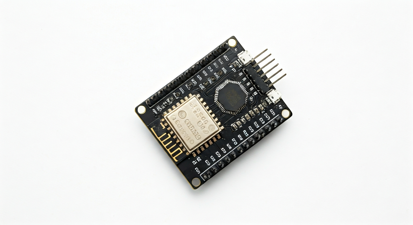
The ESP8266 NodeMCU is a popular and affordable development board that brings Wi-Fi connectivity to the ESP8266 System-on-Chip (SoC). Released around 2014, it quickly became a favorite among makers, students, and hobbyists due to its integrated Wi-Fi capabilities and ease of use, especially when programmed with the Arduino IDE. It provides a simple and cost-effective way to connect embedded projects to the internet or local networks.
At the heart of the NodeMCU is the ESP8266EX chip, a highly integrated Wi-Fi System-on-Chip developed by Espressif Systems. This chip includes a Tensilica L106 Diamond 32-bit RISC microcontroller core, operating at up to 160 MHz, along with a full TCP/IP stack and network management capabilities. This means the ESP8266 can handle network communication without needing a separate Wi-Fi module, making it ideal for standalone Wi-Fi projects.
The NodeMCU board itself is an evolution of earlier ESP8266 modules like the ESP-01. It features a more convenient breadboard-friendly form factor, an onboard USB-to-serial converter (usually a CH340G or CP2102), voltage regulation, and access to most of the ESP8266's GPIO pins. This makes it significantly easier to prototype with compared to bare modules. It's particularly well-suited for projects requiring internet connectivity, such as weather stations, remote sensor monitoring, smart home devices, and web servers.
While part of the broader Espressif family, the ESP8266 NodeMCU predates the more powerful ESP32 series. It offers a robust set of features for its price point, making it an excellent starting point for anyone looking to explore Wi-Fi enabled embedded systems. Its widespread adoption has led to a vast community, extensive libraries, and numerous tutorials, ensuring ample support for beginners and experienced engineers alike.
Watch
Related video, embedded from YouTube.
Specifications
| Microcontroller / SoC | ESP8266EX |
| Architecture | 32-bit RISC (Tensilica L106) |
| Clock speed | Typically 80 MHz, can be overclocked to 160 MHz |
| Flash / Storage | 4 MB (typically, varies by module) |
| RAM / SRAM | 64 KB SRAM (instruction and data RAM), 96 KB IRAM (instruction RAM) |
| Operating voltage | 3.3V |
| Digital I/O pins | 11 (exposed on headers, some with shared functions) |
| Analog / ADC | 1x 10-bit ADC (ADC0, typically connected to a voltage divider for battery monitoring) |
| PWM | Up to 4 channels (software PWM on most GPIOs) |
| Connectivity | Wi-Fi 802.11 b/g/n |
| USB | Micro-USB connector (for power and programming via CH340G/CP2102 USB-to-serial chip) |
| Power input | 5V via Micro-USB or VIN pin; 3.3V via 3.3V pin |
| Dimensions | Approx. 49mm x 25mm (standard NodeMCU v1.0 layout) |
Pinout & pin functions
| Pin | Function |
|---|---|
| Vin | 5V power input (typically through onboard regulator) |
| GND | Ground |
| 3V3 | 3.3V output (from onboard regulator) |
| EN | Chip Enable (High to enable, Low to reset) |
| D0 (GPIO16) | GPIO, Wake from deep sleep |
| D1 (GPIO5) | GPIO, I2C SCL |
| D2 (GPIO4) | GPIO, I2C SDA |
| D3 (GPIO0) | GPIO, Boot mode select (Low during boot enters flash mode) |
| D4 (GPIO2) | GPIO, Boot mode select (High during boot) |
| D5 (GPIO14) | GPIO, SPI SCK |
| D6 (GPIO12) | GPIO, SPI MISO, also has internal pull-down |
| D7 (GPIO13) | GPIO, SPI MOSI, also has internal pull-down |
| D8 (GPIO15) | GPIO, SPI CS, also has internal pull-down, Boot mode select (Low during boot) |
| RX (GPIO3) | UART RX, also has internal pull-down |
| TX (GPIO1) | UART TX, also has internal pull-down |
| ADC (A0) | 10-bit Analog to Digital Converter (ADC0) |
| RST | Reset pin (connected to EN) |
Wiring & circuit basics
Powering the NodeMCU requires careful attention to voltage levels. The board typically has an onboard 3.3V voltage regulator and a micro-USB port that accepts 5V. You can power the board by connecting a 5V supply to the micro-USB port or the VIN pin. The onboard regulator will then provide a stable 3.3V for the ESP8266 chip and any 3.3V peripherals you connect. Avoid connecting voltages higher than 3.3V directly to the ESP8266's GPIO pins, as this can damage the chip.
When interfacing with other components, always remember that the ESP8266 NodeMCU operates at 3.3V logic levels. Connecting 5V devices directly to its GPIO pins can cause permanent damage. If you need to connect a 5V sensor or actuator, use a logic level shifter. Conversely, if you are connecting a 3.3V device to a 5V microcontroller (like an Arduino Uno), you will need a level shifter to boost the signal to 5V.
A simple LED circuit demonstrates basic wiring. Connect an LED's anode (longer leg) to a digital GPIO pin (e.g., D4/GPIO2) through a current-limiting resistor (typically 220-330 ohms). Connect the LED's cathode (shorter leg) to a GND pin. When the GPIO pin is set HIGH (3.3V), current flows through the resistor and LED, illuminating it. When set LOW (0V), the LED turns off. For I2C communication, connect the sensor's SDA pin to D2 (GPIO4) and the SCL pin to D1 (GPIO5), along with power (3.3V) and ground connections.
Programming & getting started
The ESP8266 NodeMCU is highly versatile in its programming options. The most common and beginner-friendly approach is using the Arduino IDE. You'll need to install the ESP8266 board support package via the Board Manager. Once installed, you can select the 'NodeMCU 1.0 (ESP-12E Module)' or similar from the board list. Connect the NodeMCU via USB, select the correct COM port, and upload your sketch. Libraries for Wi-Fi, HTTP, MQTT, and various sensors are readily available.
Alternatively, you can program the NodeMCU using MicroPython or CircuitPython, which offer a Python-based development experience. For more advanced control and bare-metal programming, the Espressif IoT Development Framework (ESP-IDF) is the official SDK. PlatformIO, an integrated development environment for IoT development, also offers excellent support for the ESP8266 and integrates well with various editors like VS Code.