Raspberry Pi 1 Model B+: A Deep Dive into the Classic Single-Board Computer
Explore the capabilities and legacy of the Raspberry Pi 1 Model B+, a foundational single-board computer for education and hobbyist projects.
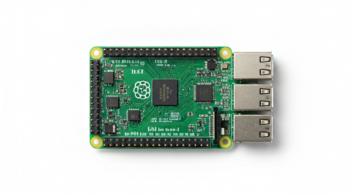
The Raspberry Pi 1 Model B+ is a significant iteration in the Raspberry Pi family, released in July 2014. It builds upon the success of its predecessors, offering a more refined and feature-rich experience for makers, students, and embedded engineers. This board was designed with education as a primary goal, aiming to bring affordable and accessible computing power to classrooms and homes worldwide, fostering an interest in programming and electronics.
At its heart, the Raspberry Pi 1 Model B+ is powered by the Broadcom BCM2835 system-on-a-chip (SoC). This ARM11-based processor, clocked at 700 MHz, was a capable choice for its time, handling various computing tasks and embedded applications. While not as powerful as later Raspberry Pi models, the BCM2835 provides a solid foundation for learning and experimenting with Linux-based operating systems and hardware interfacing.
The Model B+ distinguished itself from earlier models with several key improvements. It increased the number of GPIO pins to 40, offering greater flexibility for connecting external hardware. It also featured improved power management, with a lower current draw and a micro USB power connector. The inclusion of a micro SD card slot for storage and a standard HDMI output made it a more complete and user-friendly computing platform for its target audience.
This board is particularly well-suited for beginners looking to understand the fundamentals of single-board computers, Linux, and basic electronics. It's ideal for projects involving simple sensor readings, controlling LEDs, learning about networking, or running lightweight applications. While it may struggle with demanding tasks like high-definition video processing or complex machine learning models, its robust GPIO capabilities and extensive community support make it a valuable tool for educational purposes and many hobbyist projects.
Watch
Related video, embedded from YouTube.
Specifications
| Microcontroller / SoC | Broadcom BCM2835 |
| Architecture | ARMv6-compatible |
| Clock speed | 700 MHz |
| Flash / Storage | Micro SD card slot (up to 32GB recommended) |
| RAM / SRAM | 512 MB DDR2 SDRAM |
| Operating voltage | 3.3V |
| Digital I/O pins | 40 GPIO |
| Analog / ADC | None (requires external ADC) |
| PWM | Yes (software-based, limited hardware support) |
| Connectivity | 10/100 Ethernet, Wi-Fi (via USB dongle), Bluetooth (via USB dongle) |
| USB | 4 x USB 2.0 ports |
| Power input | 5V micro USB |
| Dimensions | 85.6 mm x 56.5 mm |
Pinout & pin functions
| Pin | Function |
|---|---|
| 3.3V | Power output (3.3V) |
| 5V | Power output (5V) |
| GND | Ground |
| GPIO 0 | General Purpose Input/Output |
| GPIO 1 | General Purpose Input/Output |
| GPIO 2 | General Purpose Input/Output (I2C SDA) |
| GPIO 3 | General Purpose Input/Output (I2C SCL) |
| GPIO 4 | General Purpose Input/Output |
| GPIO 5 | General Purpose Input/Output (SPI MOSI) |
| GPIO 6 | General Purpose Input/Output (SPI MISO) |
| GPIO 7 | General Purpose Input/Output (SPI SCLK) |
| GPIO 8 | General Purpose Input/Output (SPI CE0) |
| GPIO 9 | General Purpose Input/Output (SPI CE1) |
| GPIO 10 | General Purpose Input/Output |
| GPIO 11 | General Purpose Input/Output |
| GPIO 12 | General Purpose Input/Output |
| GPIO 13 | General Purpose Input/Output |
| GPIO 14 | General Purpose Input/Output (UART TXD) |
| GPIO 15 | General Purpose Input/Output (UART RXD) |
| GPIO 16 | General Purpose Input/Output |
| GPIO 17 | General Purpose Input/Output |
| GPIO 18 | General Purpose Input/Output |
| GPIO 19 | General Purpose Input/Output |
| GPIO 20 | General Purpose Input/Output |
| GPIO 21 | General Purpose Input/Output |
| GPIO 22 | General Purpose Input/Output |
| GPIO 23 | General Purpose Input/Output |
| GPIO 24 | General Purpose Input/Output |
| GPIO 25 | General Purpose Input/Output |
| GPIO 26 | General Purpose Input/Output |
| GPIO 27 | General Purpose Input/Output |
| RUN | System reset (active low) |
| ID SD | Serial EEPROM Data |
| ID SC | Serial EEPROM Clock |
| 4x USB 2.0 | Connect USB devices |
| Ethernet | 10/100 Mbps Ethernet port |
| HDMI | Video and audio output |
| Audio Jack | 3.5mm audio and composite video output |
| Micro USB | Power input |
| Micro SD Card Slot | Operating system and storage |
Wiring & circuit basics
Powering the Raspberry Pi 1 Model B+ requires a stable 5V power supply delivered via the micro USB port. A minimum current rating of 1A is recommended, with 2A being preferable, especially if you are powering multiple peripherals through the USB ports. The board has onboard voltage regulators to provide the necessary 3.3V for its components and the GPIO pins. It is crucial to use a high-quality power supply to avoid brownouts and potential data corruption, which can occur if the voltage drops too low.
The GPIO pins on the Raspberry Pi 1 Model B+ operate at 3.3V logic levels. This is a critical consideration when interfacing with external components. Connecting a 5V device directly to a 3.3V input pin can damage the Raspberry Pi. Conversely, if you are using 5V sensors or actuators, you may need a level shifter to convert the 3.3V GPIO signals to 5V. Always check the voltage requirements of your external components before connecting them to the Raspberry Pi.
For example, to blink an LED, connect the longer leg (anode) of the LED to a GPIO pin (e.g., GPIO 17) through a current-limiting resistor (typically 220-330 ohms). Connect the shorter leg (cathode) of the LED to a Ground (GND) pin on the Raspberry Pi. When you set GPIO 17 to HIGH in your program, current flows through the resistor and LED, causing it to light up. Setting it to LOW will turn the LED off.
Programming & getting started
The Raspberry Pi 1 Model B+ primarily runs a Linux-based operating system, typically Raspberry Pi OS (formerly Raspbian). This allows for a wide range of programming languages and tools. For embedded development and hardware interaction, Python (with libraries like RPi.GPIO or gpiozero) is a very popular and beginner-friendly choice. You can write Python scripts directly on the Raspberry Pi or develop them on a separate computer and transfer them.
To get started, flash Raspberry Pi OS onto a micro SD card using a tool like Raspberry Pi Imager. Insert the SD card into the Pi, connect a monitor, keyboard, and mouse, and power it on. Once the OS has booted, you can open a terminal or an IDE like Thonny (often pre-installed) to write and run your first Python program. For example, to blink an LED, you would write a Python script that configures a GPIO pin as an output and toggles its state.