Raspberry Pi 3 Model B: A Deep Dive for Makers and Engineers
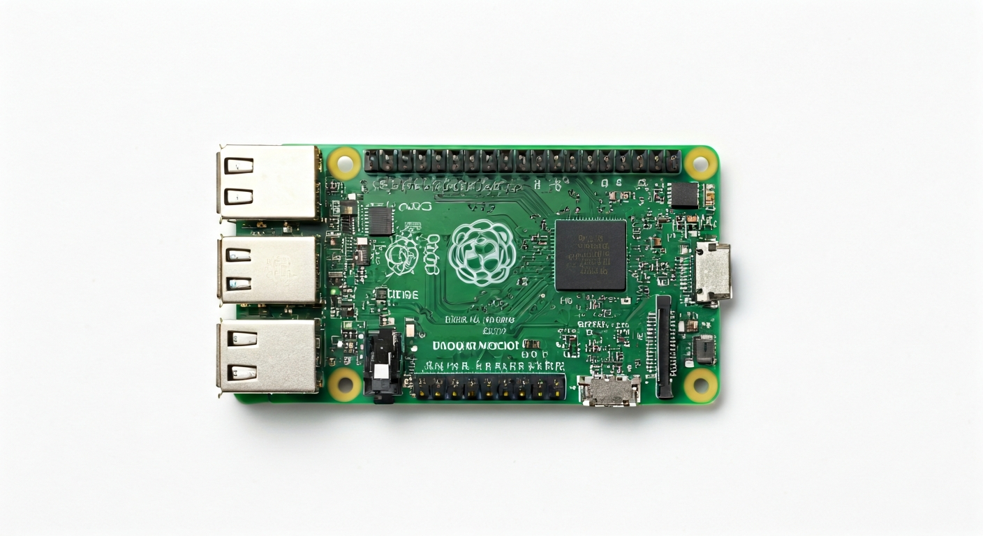
The Raspberry Pi 3 Model B brought significant performance and connectivity upgrades to the popular single-board computer family, making it a versatile platform for a wide range of projects.
The Raspberry Pi 3 Model B, released in February 2016, represented a substantial leap forward for the Raspberry Pi Foundation's single-board computer line. It was designed to offer a more powerful and connected computing experience for education, hobbyists, and professionals alike. This iteration moved beyond the basic computing capabilities of its predecessors, integrating features that made it suitable for more demanding applications, including embedded systems development, media centers, and even light desktop use.
At its heart, the Raspberry Pi 3 Model B is powered by the Broadcom BCM2837 System-on-Chip (SoC). This SoC features a 64-bit quad-core ARM Cortex-A53 processor running at 1.2 GHz. This was a significant upgrade from the dual-core Cortex-A7 in the Raspberry Pi 2 Model B, providing a noticeable boost in processing power. The BCM2837 also integrates a VideoCore IV GPU, which handles graphics and video output, enabling smooth HD playback and basic graphical interfaces.
Positioned as a mid-range board in the Raspberry Pi family at its release, the 3 Model B offered a compelling balance of performance, features, and cost. It retained the familiar 40-pin GPIO header, ensuring backward compatibility with many existing HATs and accessories, while introducing onboard Wi-Fi and Bluetooth connectivity. This integrated wireless capability eliminated the need for external dongles, simplifying builds and reducing costs for connected projects. It remains a popular choice for makers who need a capable, low-cost computer for projects requiring networking and moderate processing power.
The Raspberry Pi 3 Model B is ideal for makers, students, and embedded engineers looking for a robust platform that bridges the gap between microcontrollers like Arduino and full-fledged PCs. Its Linux-based operating system (Raspberry Pi OS, formerly Raspbian) provides a familiar environment for software development, while the GPIO pins offer direct hardware interaction. It's well-suited for projects involving IoT, robotics, home automation, learning programming, and experimenting with embedded Linux systems.
Watch
Related video, embedded from YouTube.
Specifications
| Microcontroller / SoC | Broadcom BCM2837 |
| Architecture | 64-bit ARM Cortex-A53 |
| Clock speed | 1.2 GHz (quad-core) |
| Flash / Storage | MicroSD card slot (up to 32GB officially recommended, but larger cards often work) |
| RAM / SRAM | 1 GB LPDDR2 SDRAM |
| Operating voltage | 3.3V (for GPIO and onboard peripherals) |
| Digital I/O pins | 40 GPIO pins (programmable) |
| Analog / ADC | None (requires external ADC module) |
| PWM | Up to 6 hardware PWM channels (shared with other functions) |
| Connectivity | Onboard 802.11 b/g/n Wi-Fi, Bluetooth 4.1 (BLE) |
| USB | 4 x USB 2.0 Type-A ports |
| Power input | 5V DC via Micro USB connector (minimum 2.5A recommended) or 5V via GPIO header |
| Dimensions | 85mm x 56mm |
Pinout & pin functions
| Pin | Function |
|---|---|
| 3.3V | 3.3V Power Output |
| 5V | 5V Power Output |
| 5V | 5V Power Output |
| GND | Ground |
| GPIO2 | I2C SDA |
| GND | Ground |
| GPIO3 | I2C SCL |
| GND | Ground |
| GPIO4 | General Purpose I/O |
| GPIO17 | General Purpose I/O |
| GND | Ground |
| GPIO27 | General Purpose I/O |
| GPIO22 | General Purpose I/O |
| GND | Ground |
| GPIO18 | PWM0, I2S PCM CLK |
| GPIO23 | General Purpose I/O |
| GND | Ground |
| GPIO24 | General Purpose I/O |
| GPIO25 | PWM1, I2S PCM FSYNC |
| GND | Ground |
| GPIO8 | SPI MOSI |
| GPIO7 | SPI CE1 |
| GND | Ground |
| GPIO9 | SPI MISO |
| GPIO11 | SPI SCLK |
| GND | Ground |
| GPIO5 | General Purpose I/O |
| GPIO6 | General Purpose I/O |
| GND | Ground |
| GPIO12 | PWM0 |
| GPIO13 | PWM1 |
| GND | Ground |
| GPIO19 | PWM0, I2S PCM TX |
| GPIO16 | General Purpose I/O |
| GND | Ground |
| GPIO26 | General Purpose I/O |
| GPIO20 | I2S PCM DIN |
| GND | Ground |
| GPIO21 | I2S PCM DOUT |
| GPIO22 | General Purpose I/O |
| GND | Ground |
| GPIO28 | I2C SDA (alternate) |
| GPIO29 | I2C SCL (alternate) |
| GND | Ground |
| GPIO30 | General Purpose I/O |
| GPIO31 | General Purpose I/O |
| GND | Ground |
| GPIO14 | UART TXD |
| GPIO15 | UART RXD |
| GND | Ground |
| ID_SD | I2C EEPROM Data |
| ID_SC | I2C EEPROM Clock |
| GND | Ground |
| GPIO1 | General Purpose I/O |
| GPIO0 | General Purpose I/O |
| GND | Ground |
| GPIO10 | SPI CS |
| GPIO9 | SPI MISO |
| GND | Ground |
| GPIO11 | SPI SCLK |
| GPIO7 | SPI CE0 |
| GND | Ground |
| GPIO8 | SPI MOSI |
| GPIO17 | General Purpose I/O |
| GND | Ground |
| GPIO18 | PWM0, I2S PCM CLK |
| GPIO27 | General Purpose I/O |
| GND | Ground |
| GPIO22 | General Purpose I/O |
| GPIO23 | General Purpose I/O |
| GND | Ground |
| GPIO24 | General Purpose I/O |
| GPIO25 | PWM1, I2S PCM FSYNC |
| GND | Ground |
| GPIO5 | General Purpose I/O |
| GPIO12 | PWM0 |
| GND | Ground |
| GPIO6 | General Purpose I/O |
| GPIO13 | PWM1 |
| GND | Ground |
| GPIO19 | PWM0, I2S PCM TX |
| GPIO16 | General Purpose I/O |
| GND | Ground |
| GPIO26 | General Purpose I/O |
| GPIO20 | I2S PCM DIN |
| GND | Ground |
| GPIO21 | I2S PCM DOUT |
| GPIO28 | I2C SDA (alternate) |
| GND | Ground |
| GPIO29 | I2C SCL (alternate) |
| GPIO30 | General Purpose I/O |
| GND | Ground |
| GPIO31 | General Purpose I/O |
| GPIO14 | UART TXD |
| GND | Ground |
| GPIO15 | UART RXD |
| GPIO2 | I2C SDA |
| GND | Ground |
| GPIO3 | I2C SCL |
| GPIO0 | General Purpose I/O |
| GND | Ground |
| GPIO1 | General Purpose I/O |
| GPIO4 | General Purpose I/O |
| GND | Ground |
| GPIO17 | General Purpose I/O |
| GPIO27 | General Purpose I/O |
| GND | Ground |
| GPIO22 | General Purpose I/O |
| GPIO10 | SPI CS |
| GND | Ground |
| GPIO9 | SPI MISO |
| GPIO11 | SPI SCLK |
| GND | Ground |
| GPIO8 | SPI MOSI |
| GPIO7 | SPI CE1 |
| GND | Ground |
| GPIO5 | General Purpose I/O |
| GPIO6 | General Purpose I/O |
| GND | Ground |
| GPIO12 | PWM0 |
| GPIO13 | PWM1 |
| GND | Ground |
| GPIO19 | PWM0, I2S PCM TX |
| GPIO16 | General Purpose I/O |
| GND | Ground |
| GPIO26 | General Purpose I/O |
| GPIO20 | I2S PCM DIN |
| GND | Ground |
| GPIO21 | I2S PCM DOUT |
| GPIO23 | General Purpose I/O |
| GND | Ground |
| GPIO24 | General Purpose I/O |
| GPIO25 | PWM1, I2S PCM FSYNC |
| GND | Ground |
| GPIO31 | General Purpose I/O |
| GPIO14 | UART TXD |
| GND | Ground |
| GPIO15 | UART RXD |
| GPIO30 | General Purpose I/O |
| GND | Ground |
| GPIO28 | I2C SDA (alternate) |
| GPIO29 | I2C SCL (alternate) |
Wiring & circuit basics
Powering the Raspberry Pi 3 Model B requires a stable 5V DC supply. The primary method is through the Micro USB port, which is rated for a minimum of 2.5A to ensure stable operation, especially when peripherals are connected. Alternatively, power can be supplied via the 5V pins on the GPIO header, but this bypasses the onboard power regulation and requires careful attention to voltage and current. It is crucial to use a high-quality power supply designed for Raspberry Pi or similar devices to avoid voltage drops or instability, which can lead to system crashes or SD card corruption.
The Raspberry Pi 3 Model B operates at a logic level of 3.3V. This means that any sensors, LEDs, or other components directly connected to the GPIO pins must be compatible with 3.3V logic. Connecting 5V devices directly to the GPIO pins without level shifting can permanently damage the Raspberry Pi. For example, to safely connect an LED, you would connect it in series with a current-limiting resistor (typically 220-330 ohms for standard LEDs) between a GPIO pin and ground, or between a 3.3V pin and ground. The resistor value should be calculated based on the LED's forward voltage and current requirements to prevent overcurrent.
For connecting more complex peripherals like I2C sensors (e.g., an MPU6050 accelerometer/gyroscope), you would use the dedicated I2C pins. For the Raspberry Pi 3 Model B, these are typically GPIO2 (SDA) and GPIO3 (SCL). You would connect the sensor's SDA pin to GPIO2, its SCL pin to GPIO3, its VCC pin to a 3.3V pin on the Raspberry Pi, and its GND pin to a ground pin. Some I2C devices may require a pull-up resistor on the SDA and SCL lines, although many modern sensors include these onboard or the Raspberry Pi OS has them enabled by default in software. Always consult the sensor's datasheet for specific wiring requirements.
Programming & getting started
The Raspberry Pi 3 Model B primarily runs Raspberry Pi OS (a Debian-based Linux distribution), offering a wide range of programming options. For general-purpose programming, Python is extremely popular and well-supported, with libraries like RPi.GPIO or gpiozero making hardware interaction straightforward. You can write Python scripts directly on the Pi or remotely. For more system-level development or if you prefer a C/C++ environment, you can use tools like GCC and libraries like wiringPi (though it's now deprecated, alternatives exist) or the official Broadcom VCHIQ/BCMHost APIs. For embedded C development, PlatformIO is an excellent choice, supporting cross-compilation and integrated debugging.
To upload your first program (e.g., a Python script to blink an LED), you would typically connect to your Raspberry Pi 3 Model B via SSH after booting it with Raspberry Pi OS. Once logged in, you can write a Python script using a text editor like nano. For instance, to blink an LED connected to GPIO17: `import RPi.GPIO as GPIO; import time; GPIO.setmode(GPIO.BCM); GPIO.setup(17, GPIO.OUT); while True: GPIO.output(17, GPIO.HIGH); time.sleep(1); GPIO.output(17, GPIO.LOW); time.sleep(1)`. Save this as `blink.py`. Then, run it from the terminal using `sudo python3 blink.py`. The `sudo` is often required for direct GPIO access.