Raspberry Pi 400: The Complete MakerLab Reference
A powerful single-board computer integrated into a compact keyboard, perfect for learning, coding, and prototyping.
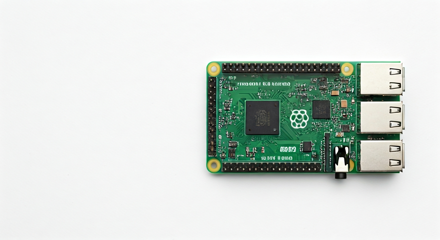
The Raspberry Pi 400 is a unique and versatile single-board computer built directly into a compact, retro-style keyboard. Released in late 2020, it reimagines the classic personal computer experience for a new generation of makers, students, and hobbyists. It integrates a Raspberry Pi 4 Model B into the keyboard's PCB, offering a familiar and accessible computing platform without the need for external peripherals beyond a mouse and display.
At its heart, the Raspberry Pi 400 is powered by the Broadcom BCM2711 system-on-a-chip (SoC), the same powerful quad-core ARM Cortex-A72 processor found in the Raspberry Pi 4. This SoC provides significant processing power, making the Pi 400 suitable for a wide range of tasks, from web browsing and document editing to more demanding applications like light programming, media playback, and even some light gaming. The integration into a keyboard form factor simplifies setup and reduces clutter, making it an ideal choice for educational settings or as a primary desktop replacement for basic computing needs.
Compared to other Raspberry Pi boards, the Pi 400 offers a more complete, out-of-the-box computing experience. While boards like the Raspberry Pi Pico are microcontrollers focused on embedded projects, and the standard Raspberry Pi 4 is a bare board requiring a separate case and keyboard, the Pi 400 is a self-contained unit. This makes it less ideal for deeply embedded projects requiring minimal footprint or extreme environmental resilience, but perfect for users who want a capable, general-purpose computer that can also be used for learning about electronics and programming through its accessible GPIO pins.
The target audience for the Raspberry Pi 400 includes students learning to code, aspiring developers, educators, and makers who want a single device that can serve as both a learning tool and a functional computer. Its plug-and-play nature, coupled with the vast ecosystem of Raspberry Pi software and accessories, makes it an excellent entry point into the world of computing and embedded systems. The integrated design also adds a layer of durability and convenience, reducing the number of separate components to manage.
Watch
Related video, embedded from YouTube.
Specifications
| Microcontroller / SoC | Broadcom BCM2711 |
| Architecture | 64-bit Quad-core ARM Cortex-A72 |
| Clock speed | 1.8 GHz (overclocked from 1.5 GHz on standard Pi 4) |
| Flash / Storage | MicroSD card slot (OS and storage) |
| RAM / SRAM | 4GB LPDDR4-3200 SDRAM |
| Operating voltage | 5V DC (via USB-C) |
| Digital I/O pins | 40-pin GPIO header (standard Raspberry Pi header) |
| Analog / ADC | — |
| PWM | Yes (via software/GPIO) |
| Connectivity | Gigabit Ethernet, Dual-band 802.11ac Wi-Fi, Bluetooth 5.0 |
| USB | 2x USB 3.0, 2x USB 2.0 |
| Power input | 5V DC, 3A via USB-C connector |
| Dimensions | 245 mm × 176 mm × 35 mm (keyboard unit) |
Pinout & pin functions
| Pin | Function |
|---|---|
| 3.3V | Power output (3.3V) |
| 5V | Power output (5V) |
| GND | Ground |
| GPIO17 | General Purpose Input/Output |
| GPIO18 | General Purpose Input/Output, PWM0 |
| GPIO27 | General Purpose Input/Output |
| GPIO22 | General Purpose Input/Output |
| GPIO23 | General Purpose Input/Output, SPI1 MOSI |
| GPIO24 | General Purpose Input/Output, SPI1 MISO |
| GPIO25 | General Purpose Input/Output, SPI1 SCK |
| GPIO10 | General Purpose Input/Output, SPI1 CE0 |
| GPIO9 | General Purpose Input/Output, SPI1 CE1 |
| GND | Ground |
| GPIO11 | General Purpose Input/Output, SPI0 SCK |
| GPIO5 | General Purpose Input/Output, I2C1 SCL |
| GPIO6 | General Purpose Input/Output, I2C1 SDA |
| GPIO13 | General Purpose Input/Output, PWM1 |
| GPIO19 | General Purpose Input/Output, PWM0 |
| GPIO26 | General Purpose Input/Output |
| GPIO7 | General Purpose Input/Output, SPI0 MOSI |
| GPIO8 | General Purpose Input/Output, SPI0 MISO |
| GND | Ground |
| GPIO12 | General Purpose Input/Output, PWM0 |
| GPIO16 | General Purpose Input/Output |
| GPIO20 | General Purpose Input/Output, I2C1 SDA |
| GPIO21 | General Purpose Input/Output, I2C1 SCL |
| GPIO28 | General Purpose Input/Output |
| GPIO29 | General Purpose Input/Output |
| GPIO30 | General Purpose Input/Output |
| GPIO31 | General Purpose Input/Output |
| GND | Ground |
| GPIO0 | General Purpose Input/Output |
| GPIO1 | General Purpose Input/Output, I2C0 SDA |
| GPIO2 | General Purpose Input/Output, I2C0 SCL |
| GPIO3 | General Purpose Input/Output, I2C0 SDA |
| GPIO4 | General Purpose Input/Output |
| GPIO14 | General Purpose Input/Output, UART0 TXD |
| GPIO15 | General Purpose Input/Output, UART0 RXD |
| GPIO17 | General Purpose Input/Output |
| 3.3V | Power output (3.3V) |
| GND | Ground |
| 5V | Power output (5V) |
Wiring & circuit basics
Powering the Raspberry Pi 400 is straightforward via its USB-C port, which requires a stable 5V DC supply capable of delivering at least 3A. Using the official Raspberry Pi 400 PSU or a comparable high-quality USB-C power adapter is highly recommended to prevent undervoltage issues that can lead to instability or data corruption. The board itself incorporates voltage regulation for its internal components, but external peripherals connected to the GPIO header operate at 3.3V logic levels. It is crucial to use level shifters if interfacing with 5V components to avoid damaging the Pi.
Connecting components to the GPIO header requires careful attention to pin functions. For example, to blink an LED, you would connect the LED's anode (longer leg) to a 3.3V pin (like GPIO17), then connect the LED's cathode (shorter leg) through a current-limiting resistor (typically 220-330 ohms) to a ground (GND) pin. The resistor prevents excessive current from flowing through the LED and the GPIO pin, protecting both.
For more complex sensors, like an I2C sensor (e.g., a BME280 environmental sensor), you would connect its VCC pin to a 3.3V pin on the Pi 400, its GND pin to a GND pin, its SDA pin to GPIO6 (or GPIO20), and its SCL pin to GPIO5 (or GPIO21). These specific GPIO pins are part of the I2C bus, allowing the Pi to communicate with the sensor using the I2C protocol. Always consult the sensor's datasheet and the Raspberry Pi 400 pinout diagram to ensure correct connections.
Programming & getting started
The Raspberry Pi 400, running Raspberry Pi OS (a Debian-based Linux distribution), is primarily programmed using standard Linux development tools and scripting languages. For embedded-style projects utilizing the GPIO pins, Python is the most popular choice, often using libraries like RPi.GPIO or gpiozero. You can write Python scripts directly on the Pi 400 using editors like Thonny or Geany, and run them from the terminal. For more advanced users, C/C++ with libraries like wiringPi (though deprecated, still functional) or libgpiod can be used.
To upload your first program (e.g., a Python script to blink an LED), ensure your Raspberry Pi 400 is set up with Raspberry Pi OS and connected to the internet. Open a terminal window, navigate to the directory where you saved your script (e.g., `cd Desktop`), and execute it using `python your_script_name.py`. For example, a simple script to toggle GPIO17 would involve importing the `RPi.GPIO` library, setting the pin mode, and then using `GPIO.output(17, GPIO.HIGH)` and `GPIO.output(17, GPIO.LOW)` within a loop.