Raspberry Pi Pico 2: The Next Generation of Microcontroller Power
The Raspberry Pi Pico 2 brings enhanced performance and expanded capabilities to the popular RP2040 microcontroller, making it ideal for ambitious embedded projects.
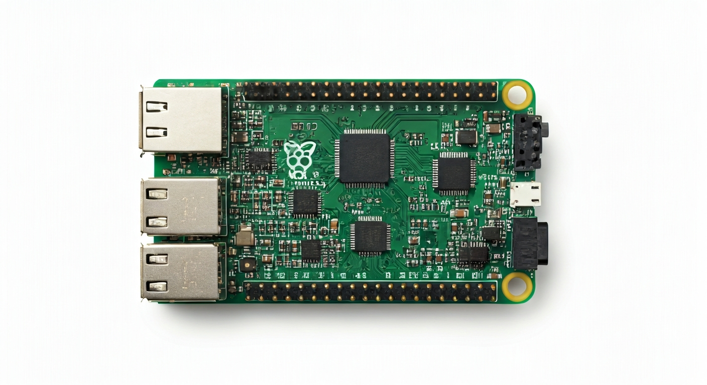
The Raspberry Pi Pico 2 is the latest iteration in Raspberry Pi's microcontroller board series, building upon the success of its predecessor. It features the RP2040-2 chip, an upgraded version of the original RP2040, offering improved performance and additional features for more demanding applications. This board is designed to be a powerful yet accessible platform for a wide range of users, from hobbyists and students learning embedded systems to professional engineers developing complex IoT devices and real-time control systems.
At the heart of the Pico 2 is the RP2040-2, a custom-designed microcontroller from Raspberry Pi. This dual-core ARM Cortex-M0+ processor running at a higher clock speed than the original RP2040 provides significant computational power for its class. The chip also boasts a larger on-chip SRAM, allowing for more complex programs and data handling. The Pico 2 retains the familiar form factor and extensive GPIO capabilities of the original Pico, ensuring compatibility with existing accessories and a smooth transition for users.
Positioned as a high-performance, low-cost microcontroller, the Pico 2 is a direct competitor to other popular boards in the embedded space. Its development was driven by the demand for more processing power and memory within the Raspberry Pi ecosystem, enabling users to tackle projects that were previously out of reach for entry-level microcontrollers. The board is particularly well-suited for applications requiring significant data processing, fast response times, or the implementation of advanced algorithms.
The Pico 2 targets makers who are looking to push the boundaries of their projects, students who need a robust platform for learning advanced embedded concepts, and engineers who require a reliable and cost-effective solution for product development. Its combination of raw power, flexible I/O, and extensive software support makes it a versatile choice for everything from simple blinking LEDs to sophisticated robotics and sensor networks.
Watch
Related video, embedded from YouTube.
Specifications
| Microcontroller / SoC | Raspberry Pi RP2040-2 |
| Architecture | Dual-core ARM Cortex-M0+ |
| Clock speed | Up to 270 MHz (configurable) |
| Flash / Storage | 2MB QSPI Flash (on-board) |
| RAM / SRAM | 320KB SRAM (on-chip) |
| Operating voltage | 3.3V |
| Digital I/O pins | 26 (multi-function) |
| Analog / ADC | 3x 12-bit (up to 500 kS/s) |
| PWM | 16 channels (available on most GPIO) |
| Connectivity | 2x SPI, 2x I2C, 2x UART |
| USB | 1x USB 1.1 (Host/Device) |
| Power input | 1.8V to 5.5V (via VSYS pin) or USB |
| Dimensions | 51mm x 21mm |
Pinout & pin functions
| Pin | Function |
|---|---|
| 3V3 | 3.3V Power Output |
| GND | Ground |
| GND | Ground |
| ADC0 (GP26) | Analog to Digital Converter input, GPIO 26 |
| ADC1 (GP27) | Analog to Digital Converter input, GPIO 27 |
| ADC2 (GP28) | Analog to Digital Converter input, GPIO 28 |
| VREF | ADC Reference Voltage |
| AGND | Analog Ground |
| GP0 | General Purpose Input/Output 0 |
| GP1 | General Purpose Input/Output 1, UART0 TX |
| GP2 | General Purpose Input/Output 2, UART0 RX |
| GP3 | General Purpose Input/Output 3, I2C0 SDA |
| GP4 | General Purpose Input/Output 4, I2C0 SCL |
| GP5 | General Purpose Input/Output 5 |
| GP6 | General Purpose Input/Output 6, SPI0 RX |
| GP7 | General Purpose Input/Output 7, SPI0 CSn |
| GP8 | General Purpose Input/Output 8, SPI0 SCK |
| GP9 | General Purpose Input/Output 9, SPI0 TX |
| GP10 | General Purpose Input/Output 10, SPI1 RX |
| GP11 | General Purpose Input/Output 11, SPI1 CSn |
| GP12 | General Purpose Input/Output 12, SPI1 SCK |
| GP13 | General Purpose Input/Output 13, SPI1 TX |
| GP14 | General Purpose Input/Output 14, UART1 TX |
| GP15 | General Purpose Input/Output 15, UART1 RX |
| GP16 | General Purpose Input/Output 16, I2C1 SDA |
| GP17 | General Purpose Input/Output 17, I2C1 SCL |
| GP18 | General Purpose Input/Output 18 |
| GP19 | General Purpose Input/Output 19 |
| GP20 | General Purpose Input/Output 20 |
| GP21 | General Purpose Input/Output 21 |
| GP22 | General Purpose Input/Output 22 |
| GP23 | General Purpose Input/Output 23 |
| GP24 | General Purpose Input/Output 24 |
| GP25 | General Purpose Input/Output 25 |
| GP28 | General Purpose Input/Output 28, ADC2 |
| RUN | Reset Pin (active low) |
| VSYS | System Power Input (1.8V to 5.5V) |
| VBUS | USB 5V Power Input |
Wiring & circuit basics
The Raspberry Pi Pico 2 operates at a logic level of 3.3V. This means all digital inputs and outputs communicate using 3.3V signals. Connecting 5V devices directly to the Pico 2's GPIO pins can damage the microcontroller. If you need to interface with 5V components, use a logic level shifter. Powering the Pico 2 can be done via the micro-USB port, which supplies 5V, or directly through the VSYS pin, which accepts a wide voltage range from 1.8V to 5.5V. The onboard 3.3V regulator can supply up to 500mA, but for higher current demands, it's advisable to power the board via VSYS with an external supply that can provide sufficient current.
A basic circuit to blink an LED involves connecting an LED's anode (longer leg) to a GPIO pin (e.g., GP15) and its cathode (shorter leg) to a current-limiting resistor (typically 220-330 Ohms for a standard LED). The other end of the resistor connects to a GND pin. When the GPIO pin is set to HIGH (3.3V), current flows through the LED and resistor to ground, illuminating the LED. This simple setup demonstrates digital output and basic circuit construction.
For interfacing with sensors, such as an I2C temperature sensor like the BMP280, you would connect the sensor's VCC to the Pico 2's 3V3 pin, GND to a GND pin, SDA to GP3 (I2C0 SDA), and SCL to GP4 (I2C0 SCL). The Pico 2's onboard pull-up resistors might be sufficient for short traces, but for longer wires or multiple I2C devices, external pull-up resistors (typically 4.7k Ohm) on both SDA and SCL lines to 3.3V are recommended. This configuration allows the microcontroller to communicate with the sensor using the I2C protocol.
Programming & getting started
The Raspberry Pi Pico 2 can be programmed using a variety of popular toolchains. For beginners, MicroPython and CircuitPython offer an accessible Python-based development environment, allowing for rapid prototyping. The official Raspberry Pi IDE or Thonny are excellent choices for uploading MicroPython code. For C/C++ development, the Pico SDK, often used with CMake, provides the most control and performance. The Arduino IDE is also a popular option, with community-provided board support packages enabling familiar Arduino programming practices. PlatformIO, a VS Code extension, offers a robust, multi-platform development environment for C/C++ and MicroPython.
To upload your first program (e.g., a MicroPython 'blink' script), you typically need to put the Pico 2 into bootloader mode. This is done by holding down the BOOTSEL button while connecting the micro-USB cable to your computer. The Pico 2 will appear as a mass storage device (like a USB drive). You then simply drag and drop the MicroPython UF2 file onto this drive. Once the file transfer is complete, the Pico 2 will reboot and start running MicroPython. For C/C++ or Arduino, you would connect the Pico 2 normally (without holding BOOTSEL) and use the respective IDE's upload function, which typically uses the UF2 bootloader or SWD debugging interface.