Raspberry Pi Pico W: The Wi-Fi Enabled Microcontroller for Makers
The Raspberry Pi Pico W brings wireless connectivity to the affordable and powerful RP2040 microcontroller, opening up a world of IoT projects.
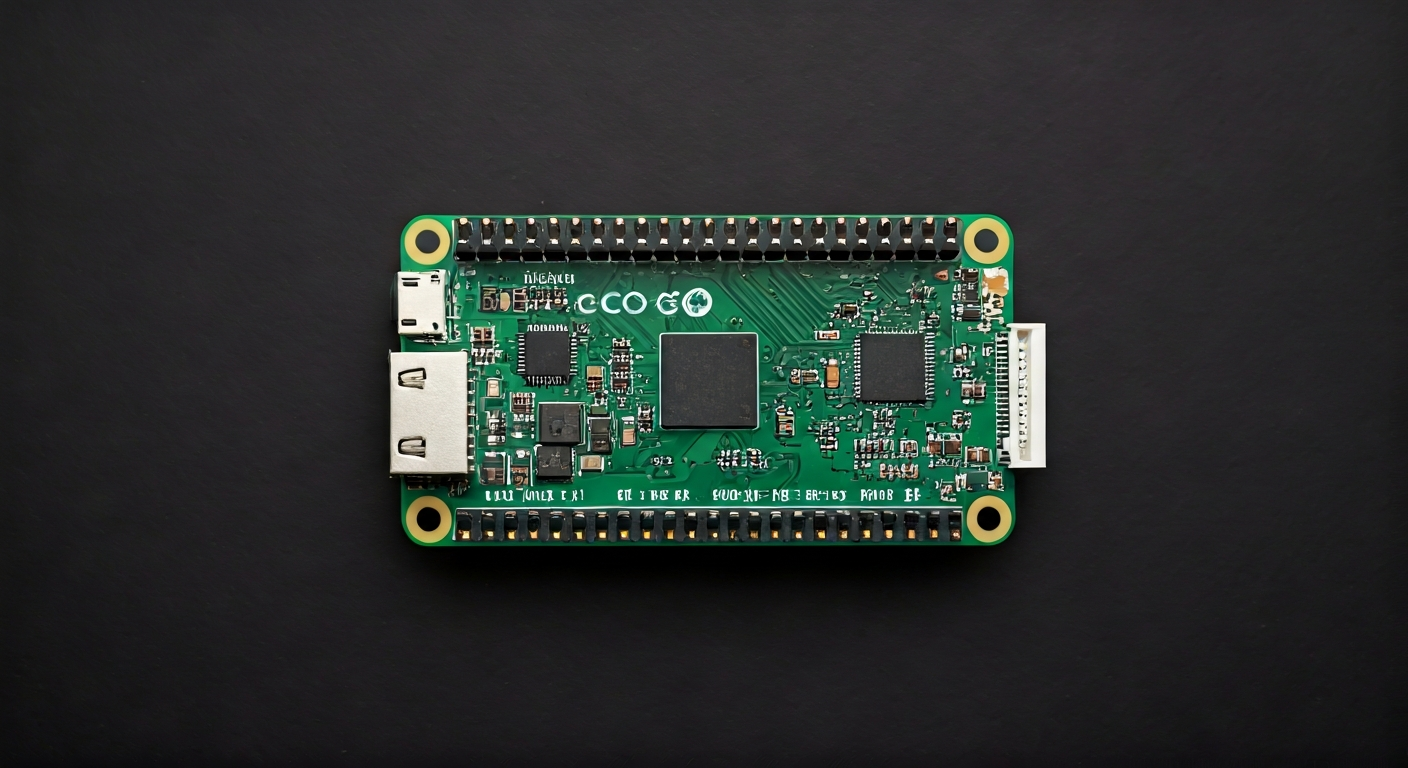
The Raspberry Pi Pico W is a low-cost, high-performance microcontroller board built around the Raspberry Pi's own RP2040 chip. It builds upon the success of the original Pico by integrating a 2.4GHz Wi-Fi and Bluetooth (BLE) module, making it an ideal choice for Internet of Things (IoT) applications. Unlike its larger Raspberry Pi siblings which run a full operating system, the Pico W is designed for embedded applications where a single program runs directly on the hardware.
At the heart of the Pico W is the RP2040 System-on-Chip (SoC), designed by Raspberry Pi in the UK. The RP2040 features a dual-core Arm Cortex-M0+ processor, capable of running at up to 133MHz. It boasts a generous amount of on-chip SRAM and supports a flexible memory map for external Flash memory. The chip also includes a range of peripherals such as SPI, I2C, UART, PWM, and ADC, all accessible through the Pico W's accessible pin headers.
Positioned as an entry-level microcontroller, the Pico W offers a compelling alternative to other development boards by combining powerful hardware with an accessible price point. The addition of wireless connectivity sets it apart from the original Pico and many other microcontrollers in its class. This makes it particularly attractive to hobbyists, students, and engineers looking to build connected projects without the complexity or cost of a full single-board computer.
The Pico W is well-suited for a wide variety of projects, from simple blinking LEDs and sensor readings to more complex applications like home automation controllers, data loggers, and remote monitoring systems. Its dual-core processor allows for tasks to be split, potentially running a network stack on one core while handling sensor input or control logic on the other. The onboard Wi-Fi enables easy integration with cloud services, web dashboards, and local networks.
Watch
Related video, embedded from YouTube.
Specifications
| Microcontroller / SoC | Raspberry Pi RP2040 |
| Architecture | Dual-core Arm Cortex-M0+ |
| Clock speed | Up to 133MHz (default) |
| Flash / Storage | 2MB (onboard QSPI Flash) |
| RAM / SRAM | 264KB (onboard SRAM) |
| Operating voltage | 3.3V |
| Digital I/O pins | 26 (multifunction) |
| Analog / ADC | 3x 12-bit (4x if internal temperature sensor not used) |
| PWM | All GPIO pins support hardware PWM |
| Connectivity | 2.4GHz Wi-Fi (802.11n), Bluetooth 5.2 (BLE) |
| USB | Micro USB 1.1 (device and host support) |
| Power input | 1.7V - 5.5V (via VSYS pin), 5V (via Micro USB) |
| Dimensions | 51mm x 21mm |
Pinout & pin functions
| Pin | Function |
|---|---|
| 3V3 | 3.3V power output |
| GND | Ground |
| GP0 | GPIO, ADC0, UART0 TX, SPI0 TX, PWM0 |
| GP1 | GPIO, ADC1, UART0 RX, SPI0 RX, PWM1 |
| GP2 | GPIO, ADC2, UART1 TX, SPI0 SCK, PWM2 |
| GP3 | GPIO, ADC3, UART1 RX, SPI0 CSn, PWM3 |
| GP4 | GPIO, SPI1 TX, PWM4 |
| GP5 | GPIO, SPI1 RX, PWM5 |
| GP6 | GPIO, SPI1 SCK, PWM6 |
| GP7 | GPIO, SPI1 CSn, PWM7 |
| GP8 | GPIO, I2C0 SDA, PWM8 |
| GP9 | GPIO, I2C0 SCL, PWM9 |
| GP10 | GPIO, I2C1 SDA, PWM10 |
| GP11 | GPIO, I2C1 SCL, PWM11 |
| GP12 | GPIO, UART0 TX, PWM12 |
| GP13 | GPIO, UART0 RX, PWM13 |
| GP14 | GPIO, UART1 TX, PWM14 |
| GP15 | GPIO, UART1 RX, PWM15 |
| GP16 | GPIO, SPI0 TX, PWM0 |
| GP17 | GPIO, SPI0 RX, PWM1 |
| GP18 | GPIO, SPI0 SCK, PWM2 |
| GP19 | GPIO, SPI0 CSn, PWM3 |
| GP20 | GPIO, SPI1 TX, PWM4 |
| GP21 | GPIO, SPI1 RX, PWM5 |
| GP22 | GPIO, SPI1 SCK, PWM6 |
| GP23 | GPIO, SPI1 CSn, PWM7 |
| GP24 | GPIO, I2C0 SDA, PWM8 |
| GP25 | GPIO, I2C0 SCL, PWM9 |
| GP26 | GPIO, ADC0, PWM10 |
| GP27 | GPIO, ADC1, PWM11 |
| GP28 | GPIO, ADC2, PWM12 |
| GP29 | GPIO, ADC3, PWM13 |
| RUN | Reset pin (active low) |
| ADC_VREF | Analog reference voltage (typically 3.3V) |
| 3V3_EN | Enables the 3.3V regulator |
| 3V3_OUT | Regulated 3.3V power output |
| VSYS | System voltage input (1.7V - 5.5V) |
Wiring & circuit basics
The Raspberry Pi Pico W operates at a logic level of 3.3V. This means that when connecting external components, ensure they are compatible with 3.3V. Connecting 5V logic devices directly to the Pico W's GPIO pins can damage the microcontroller. If you need to interface with 5V devices, use a logic level shifter. Power can be supplied via the Micro USB port (typically 5V) or directly to the VSYS pin, which accepts a voltage range of 1.7V to 5.5V. The onboard 3.3V regulator can supply up to 500mA, but it's good practice to keep current draw below 200mA from the 3V3_OUT pin to ensure stability, especially when using wireless features.
When powering the board, the Micro USB port is the simplest method, providing both power and a data connection for programming. Alternatively, supplying power through the VSYS pin allows for battery operation or higher current applications. The RUN pin can be used to reset the RP2040; pulling it low will reset the chip. The 3V3_EN pin controls the onboard 3.3V regulator, useful for power management scenarios.
A basic LED circuit involves connecting a GPIO pin (e.g., GP15) through a current-limiting resistor (typically 220-330 ohms for a standard LED) to the LED's anode, with the LED's cathode connected to a Ground (GND) pin. This allows you to control the LED by setting the GPIO pin HIGH (3.3V) or LOW (0V). For an I2C sensor like a BME280, you would connect its VCC to Pico W's 3V3_OUT, its GND to Pico W's GND, its SDA pin to GP8 (I2C0 SDA), and its SCL pin to GP9 (I2C0 SCL).
Programming & getting started
The Raspberry Pi Pico W can be programmed using several popular environments. For beginners, MicroPython and CircuitPython offer an accessible Python-based experience. You can flash a UF2 file containing the MicroPython or CircuitPython firmware onto the Pico W by holding the BOOTSEL button while plugging it into your computer via USB; it will appear as a mass storage device. Arduino IDE support is also available through board manager installations, allowing C++ programming with familiar Arduino libraries. For more advanced users, the official Raspberry Pi SDK (based on C/C++) or PlatformIO offer powerful development workflows.
To upload your first program using MicroPython, connect the Pico W to your computer via USB, ensuring it's in bootloader mode (if not already programmed). Open your MicroPython IDE (like Thonny), connect to the Pico W's MicroPython interpreter, and then open, edit, and save your script (e.g., main.py) directly to the Pico W's filesystem. For Arduino IDE, select the correct board (Raspberry Pi Pico W), choose the appropriate COM port, and click the Upload button after writing your sketch.