Raspberry Pi Zero 2 W: A Tiny Powerhouse for Embedded Projects
The Raspberry Pi Zero 2 W is a compact and affordable single-board computer that punches above its weight, offering significantly improved performance over its predecessor in a familiar form factor.
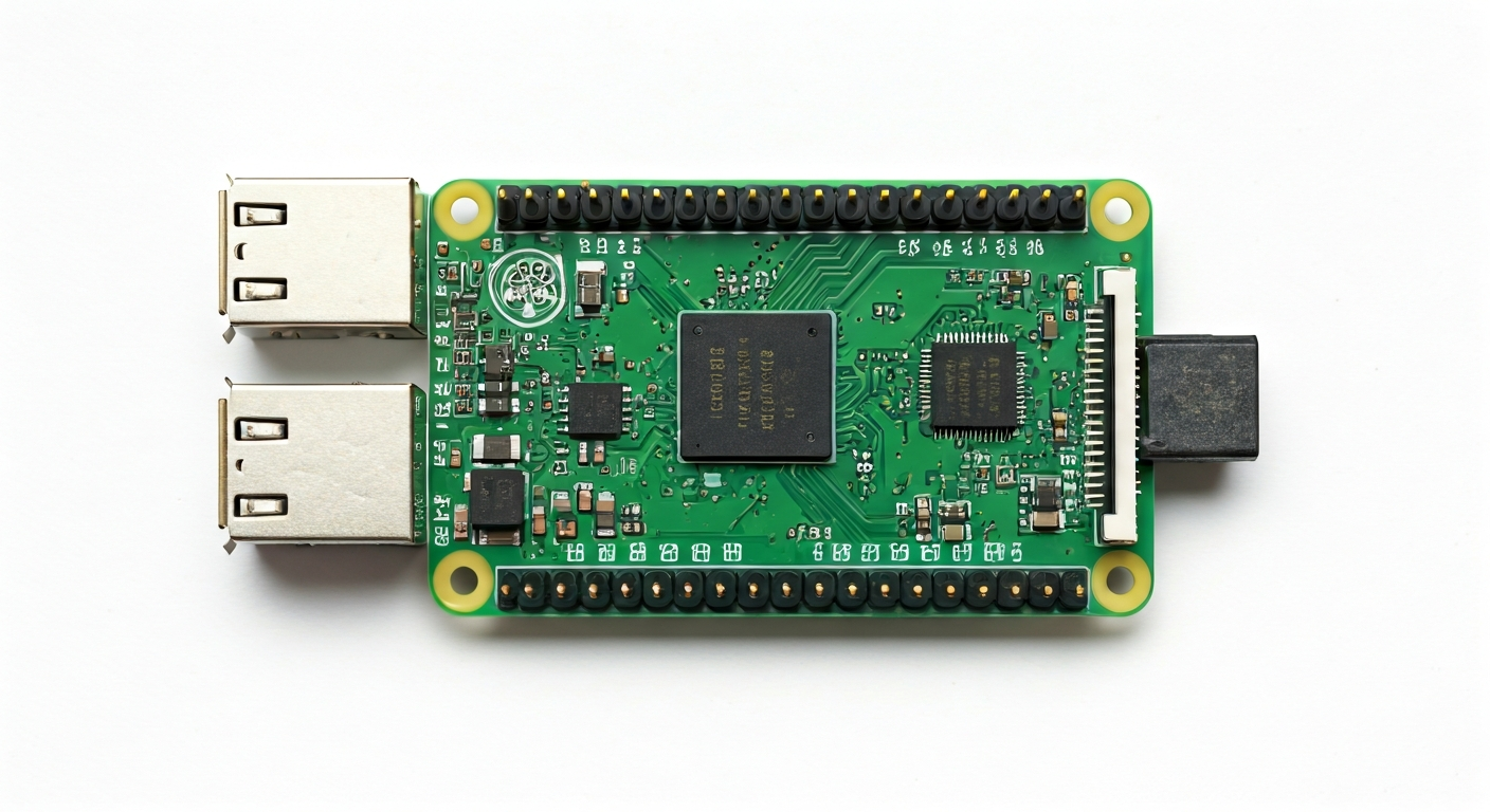
The Raspberry Pi Zero 2 W represents a substantial upgrade to the popular Raspberry Pi Zero W, bringing a much-needed performance boost while maintaining its incredibly small footprint and low cost. It's designed for makers, students, and embedded engineers who need a capable yet unobtrusive computing solution for projects where space and power efficiency are paramount.
At its heart lies the Raspberry Pi RP3A0 System-in-Package (SiP). This SiP integrates a Broadcom BCM2710A1 die (the same core processor family found in the original Raspberry Pi 3) with 512MB of LPDDR2 SDRAM. This combination provides a quad-core 64-bit ARM Cortex-A53 processor running at 1GHz, a significant leap from the single-core 1GHz processor of the Pi Zero W.
This board is ideal for projects that require more processing power than a microcontroller but can't accommodate a larger single-board computer. Think of applications like portable retro gaming consoles, compact home automation hubs, networked sensor data loggers, or even simple desktop replacements for educational purposes. Its low power consumption and small size make it perfect for battery-powered or embedded applications.
Released in October 2021, the Zero 2 W addresses the primary limitation of the original Zero W: its processing power. While the original was suitable for basic tasks, the Zero 2 W opens up possibilities for more demanding software, including heavier desktop environments, more complex IoT applications, and even light machine learning inference, all within a board that costs little more than its predecessor.
Watch
Related video, embedded from YouTube.
Specifications
| Microcontroller / SoC | Raspberry Pi RP3A0 (integrating Broadcom BCM2710A1 die) |
| Architecture | 64-bit Quad-Core ARM Cortex-A53 |
| Clock speed | 1.0 GHz |
| Flash / Storage | MicroSD card slot (card not included) |
| RAM / SRAM | 512MB LPDDR2 SDRAM |
| Operating voltage | 3.3V |
| Digital I/O pins | 17 GPIO pins |
| Analog / ADC | — |
| PWM | Yes (on specific GPIO pins) |
| Connectivity | 2.4GHz 802.11 b/g/n Wi-Fi, Bluetooth 4.2 |
| USB | 1 x Micro USB OTG port (for data/power), 1 x Micro USB power port |
| Power input | 5V via Micro USB or GPIO header |
| Dimensions | 65mm x 30mm x 5mm |
Pinout & pin functions
| Pin | Function |
|---|---|
| Pin 1 | 3.3V Power Out |
| Pin 2 | GPIO 2 (SDA1 - I2C) |
| Pin 3 | GPIO 3 (SCL1 - I2C) |
| Pin 4 | GND (Ground) |
| Pin 5 | GPIO 14 (TXD0 - UART) |
| Pin 6 | GPIO 15 (RXD0 - UART) |
| Pin 7 | GPIO 17 |
| Pin 8 | GPIO 27 |
| Pin 9 | GPIO 22 |
| Pin 10 | GPIO 11 (SCK - SPI) |
| Pin 11 | GND (Ground) |
| Pin 12 | GPIO 10 (MOSI - SPI) |
| Pin 13 | GPIO 9 (MISO - SPI) |
| Pin 14 | GPIO 25 |
| Pin 15 | GPIO 24 |
| Pin 16 | GPIO 23 |
| Pin 17 | 3.3V Power Out |
| Pin 18 | GPIO 4 |
| Pin 19 | GPIO 17 (PWM0) |
| Pin 20 | GND (Ground) |
| Pin 21 | GPIO 18 (PWM1) |
| Pin 22 | GPIO 27 |
| Pin 23 | GPIO 17 |
| Pin 24 | GPIO 22 |
| Pin 25 | GPIO 10 (SPI MOSI) |
| Pin 26 | GPIO 9 (SPI MISO) |
| Pin 27 | GPIO 11 (SPI SCK) |
| Pin 28 | GPIO 6 |
| Pin 29 | GPIO 5 |
| Pin 30 | GND (Ground) |
| Pin 31 | GPIO 13 |
| Pin 32 | GPIO 12 |
| Pin 33 | GPIO 16 |
| Pin 34 | GPIO 7 (SPI CE1) |
| Pin 35 | GPIO 8 (SPI CE0) |
| Pin 36 | GPIO 20 |
| Pin 37 | GPIO 21 |
| Pin 38 | GPIO 26 |
| Pin 39 | GND (Ground) |
| Pin 40 | GPIO 19 (PWM2) |
Wiring & circuit basics
Powering the Raspberry Pi Zero 2 W requires a stable 5V supply. The most common method is via the dedicated Micro USB power port, which should be connected to a power adapter capable of delivering at least 1.2A, though 2.5A is recommended for stable operation, especially when using Wi-Fi and peripherals. Alternatively, 5V can be supplied to Pin 1 of the 40-pin header, and Ground to Pin 6 (or any other GND pin). It's crucial to use a reliable power source to avoid brownouts and potential data corruption.
All GPIO pins on the Raspberry Pi Zero 2 W operate at 3.3V logic levels. This means you cannot directly connect 5V devices (like many standard Arduino components) to the GPIO pins without risking damage. For devices that require 5V logic, a level shifter is necessary. For example, when connecting an LED, always use a current-limiting resistor (typically 220-330 ohms) in series with the LED to protect both the LED and the GPIO pin. Connect the longer leg (anode) of the LED to the resistor, and the other end of the resistor to a GPIO pin (e.g., GPIO 17). Connect the shorter leg (cathode) of the LED to a ground pin.
For I2C communication, the SDA (Serial Data) line is typically connected to GPIO 2 (Pin 3) and the SCL (Serial Clock) line to GPIO 3 (Pin 5). Many I2C sensors, such as the BME280 environmental sensor or the MPU6050 accelerometer, also require power (3.3V from Pin 1) and ground. Ensure that the sensor's operating voltage is compatible with 3.3V. If connecting multiple I2C devices, they all share the same SDA and SCL lines, but each must have a unique address.
Programming & getting started
The Raspberry Pi Zero 2 W runs a full Linux operating system, typically Raspberry Pi OS (formerly Raspbian), which is based on Debian. This means you can program it using a wide variety of languages and tools. For Python development, you can use standard Python interpreters or frameworks like MicroPython or CircuitPython (though these are less common for the full Pi OS experience). For more complex applications or embedded development, you might use C/C++ with the GNU toolchain, or even explore Node.js.
To get started, flash Raspberry Pi OS onto a MicroSD card using a tool like Raspberry Pi Imager. Insert the card into the Zero 2 W, connect a Micro USB keyboard, mouse, and HDMI display (via a suitable adapter), and power it up. Once booted, you can connect to Wi-Fi and then use the pre-installed Thonny IDE for Python, or install other development environments like VS Code with the PlatformIO extension for more advanced embedded projects. For headless setup (without a monitor/keyboard), you can pre-configure Wi-Fi and SSH access on the SD card before booting.