Raspberry Pi Zero W: The Tiny Giant of IoT Projects
A compact, low-cost computer with built-in wireless connectivity, perfect for embedded projects and IoT.
The Raspberry Pi Zero W is a credit-card-sized single-board computer that emerged from the Raspberry Pi Foundation's need for a smaller, cheaper, and more power-efficient model for embedded and IoT applications. Released in early 2017, it builds upon the original Raspberry Pi Zero by adding onboard wireless LAN (2.4GHz 802.11n Wi-Fi) and Bluetooth 4.1 (including Bluetooth Low Energy), making it an ideal candidate for connected projects without the need for external dongles.
At its heart, the Raspberry Pi Zero W is powered by the Broadcom BCM2835 system-on-a-chip (SoC). This is a single-core processor running at 1GHz, a significant upgrade from the original Pi Zero's 700MHz clock speed. While not a powerhouse by desktop standards, this SoC provides ample processing capability for many embedded tasks, sensor data processing, and running lightweight operating systems like Raspberry Pi OS Lite or specialized embedded Linux distributions.
The 'W' in its name signifies its wireless capabilities, a crucial feature for its target audience of makers, students, and embedded engineers looking to create internet-connected devices. Its small form factor, low power consumption, and affordability make it particularly well-suited for projects where space and cost are at a premium, such as robotics, home automation, portable data loggers, and wearable technology. It retains the classic 40-pin GPIO header, offering extensive interfacing options for sensors and actuators.
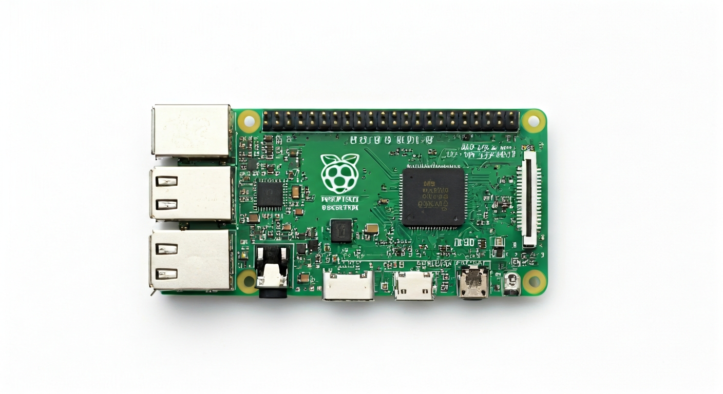
Compared to its larger siblings like the Raspberry Pi 3 or 4, the Zero W sacrifices some processing power, RAM, and a wider array of ports (like multiple USB ports or Ethernet). However, its reduced footprint and power draw are often advantages in battery-powered or space-constrained scenarios. It's a fantastic entry point for those new to Linux-based embedded systems or for experienced users needing a compact, connected compute module.
Watch
Related video, embedded from YouTube.
Specifications
| Microcontroller / SoC | Broadcom BCM2835 |
| Architecture | ARMv6-compatible |
| Clock speed | 1 GHz |
| Flash / Storage | MicroSD card slot (up to 32GB officially, often works with larger) |
| RAM / SRAM | 512 MB LPDDR2 SDRAM |
| Operating voltage | 3.3V |
| Digital I/O pins | 17 GPIO pins (accessible via 40-pin header, some shared) |
| Analog / ADC | — (No built-in ADC) |
| PWM | Software PWM available on GPIO pins |
| Connectivity | 2.4GHz 802.11b/g/n Wi-Fi, Bluetooth 4.1 (BLE) |
| USB | 1x Micro USB port (for power), 1x Micro USB OTG port (for data/peripherals) |
| Power input | 5V via Micro USB port or 5V pin on GPIO header |
| Dimensions | 65mm x 30mm x 5mm |
Pinout & pin functions
| Pin | Function |
|---|---|
| 3V3 | 3.3V Power Output |
| GND | Ground |
| GPIO2 | I2C SDA |
| GPIO3 | I2C SCL |
| GPIO4 | General Purpose Input/Output |
| GPIO17 | General Purpose Input/Output |
| GPIO27 | General Purpose Input/Output |
| GPIO22 | General Purpose Input/Output |
| GPIO5 | General Purpose Input/Output |
| GPIO6 | General Purpose Input/Output |
| GPIO13 | General Purpose Input/Output |
| GPIO19 | General Purpose Input/Output |
| GPIO26 | General Purpose Input/Output |
| GND | Ground |
| GPIO12 | General Purpose Input/Output |
| GPIO16 | General Purpose Input/Output |
| GPIO20 | General Purpose Input/Output |
| GPIO21 | General Purpose Input/Output |
| GND | Ground |
| GPIO7 | SPI MOSI |
| GPIO8 | SPI MISO |
| GPIO11 | SPI SCK |
| GPIO9 | SPI CS0 |
| GPIO10 | SPI CS1 |
| GPIO24 | General Purpose Input/Output |
| GPIO25 | General Purpose Input/Output |
| GND | Ground |
| GPIO23 | General Purpose Input/Output |
| GPIO18 | General Purpose Input/Output |
| GPIO15 | General Purpose Input/Output |
| GPIO14 | General Purpose Input/Output |
| GND | Ground |
| GPIO28 | Unused |
| GPIO29 | Unused |
| GPIO30 | Unused |
| GPIO31 | Unused |
| GPIO32 | Unused |
| GPIO33 | Unused |
| GND | Ground |
| GPIO34 | Unused |
| GPIO35 | Unused |
| 5V | 5V Power Output |
| GND | Ground |
| GPIO0 | General Purpose Input/Output |
| GPIO1 | General Purpose Input/Output |
| RUN | System Reset (Active Low) |
Wiring & circuit basics
Powering the Raspberry Pi Zero W requires a stable 5V supply. The most common method is via its Micro USB power port, which should be connected to a reliable power source capable of delivering at least 1A, and ideally 1.5A to 2A, especially when using Wi-Fi or Bluetooth. Connecting a 5V power supply to the '5V' pin on the GPIO header is also possible but requires more care to ensure correct polarity and voltage. The board itself operates at 3.3V logic levels for its GPIO pins. Connecting 5V signals directly to these pins can damage the Pi Zero W. Always use level shifters or voltage dividers if interfacing with 5V components.
When connecting external components like LEDs, it's crucial to use current-limiting resistors to prevent damage to both the LED and the Pi Zero W's GPIO pins. For a standard LED with a forward voltage of 2V and a desired current of 10mA, connected to a 3.3V GPIO pin, a resistor value of approximately (3.3V - 2V) / 0.01A = 130 Ohms is suitable. A common value like 220 or 330 Ohms would also work safely. Connect the GPIO pin to one end of the resistor, the other end of the resistor to the LED's anode (longer leg), and the LED's cathode (shorter leg) to a ground (GND) pin.
For I2C communication with sensors, the Pi Zero W utilizes GPIO2 (SDA) and GPIO3 (SCL). Connect the sensor's VCC to a 3.3V pin, its GND to a GND pin, its SDA pin to GPIO2, and its SCL pin to GPIO3. Most I2C sensors will also require pull-up resistors on the SDA and SCL lines, typically in the range of 4.7k Ohms to 10k Ohms, connected from each line to the 3.3V supply. Refer to the sensor's datasheet for specific requirements.
Programming & getting started
The Raspberry Pi Zero W runs a full Linux operating system, typically Raspberry Pi OS (formerly Raspbian). This means you have a vast range of programming options. For embedded C/C++ development, you can use tools like GCC and libraries like WiringPi or libgpiod. For Python, the language is highly popular: you can use standard Python with libraries such as RPi.GPIO or gpiozero, or even MicroPython for a more bare-metal feel. For web-connected projects, Node.js is also a strong contender.
To get started, you'll need to flash Raspberry Pi OS onto a MicroSD card. This involves downloading the OS image, using a tool like Raspberry Pi Imager or Balena Etcher to write it to the card, and then inserting the card into the Pi Zero W. For headless setup (without a monitor), you can pre-configure Wi-Fi and enable SSH by creating specific files (wpa_supplicant.conf and an empty ssh file) in the boot partition of the SD card. Once booted, you can connect to it remotely via SSH from another computer on the same network and start coding.